
Process flow thermocouple

a technology of thermocouples and fluids, applied in the direction of heat measurement, instruments, measurement devices, etc., can solve the problems of slow reaction time and difficulty in getting access to fluids, and achieve the effects of accurate and rapid detection of fluid temperature, accurate temperature measurement, and slow reaction tim

Inactive Publication Date: 2008-06-03
TOKYO ELECTRON LTD
View PDF342 Cites 58 Cited by
  • Summary
  • Abstract
  • Description
  • Claims
  • Application Information

AI Technical Summary

Benefits of technology

Enables accurate and rapid temperature measurement of fluids in process tubing by ensuring direct contact between the thermocouple and the fluid, while allowing for easy replacement and maintenance.

Problems solved by technology

However, when the temperature to be measured is that of a fluid flowing within tubing, it is difficult to get access to the fluid.
If the sensor is not in direct contact with the fluid, the reaction time is slow.

Method used


Image

  • Process flow thermocouple
  • Process flow thermocouple
  • Process flow thermocouple

Examples


Embodiment Construction

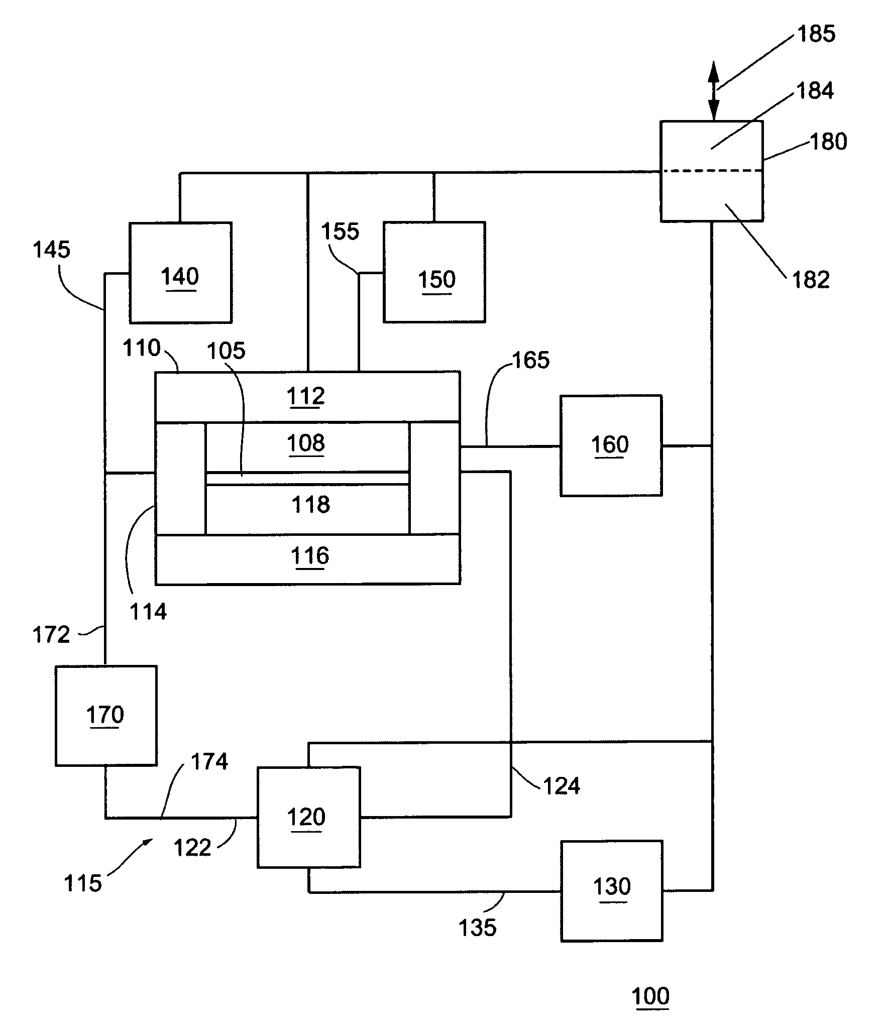
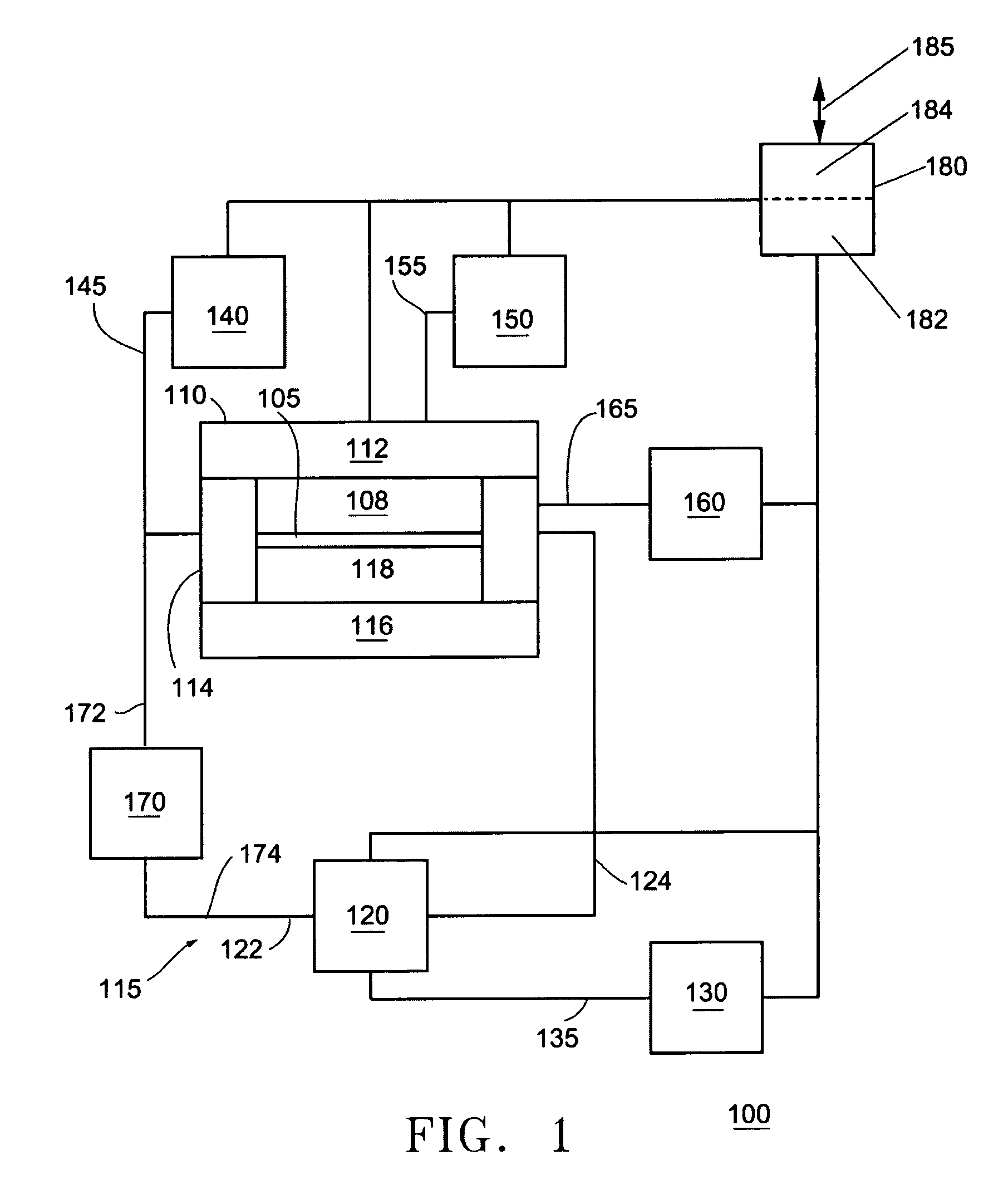
[0019]Embodiments of the present invention disclose a sensor assembly that enables in situ monitoring of the temperature of a high-pressure processing fluid / solution enclosed within a closed loop environment. The closed loop environment is preferably under high pressure. In the preferred embodiment, the high-pressure system can exceed 3,000 psi.

[0020]FIG. 1 shows an exemplary block diagram of a processing system in accordance with an embodiment of the invention. In the illustrated embodiment, processing system 100 comprises a process module 110, a recirculation system 120, a process chemistry supply system 130, a high-pressure fluid supply system 140, an exhaust control system 150, a pressure control system 160, a sensor assembly 170, and a controller 180. The processing system 100 can operate at pressures that can range from 1000 psi. to 10,000 psi. In addition, the processing system 100 can operate at temperatures that can range from 40 to 300 degrees Celsius.

[0021]The details con...


PUM

PropertyMeasurementUnit
diameteraaaaaaaaaa
diameteraaaaaaaaaa
lengthaaaaaaaaaa

Abstract

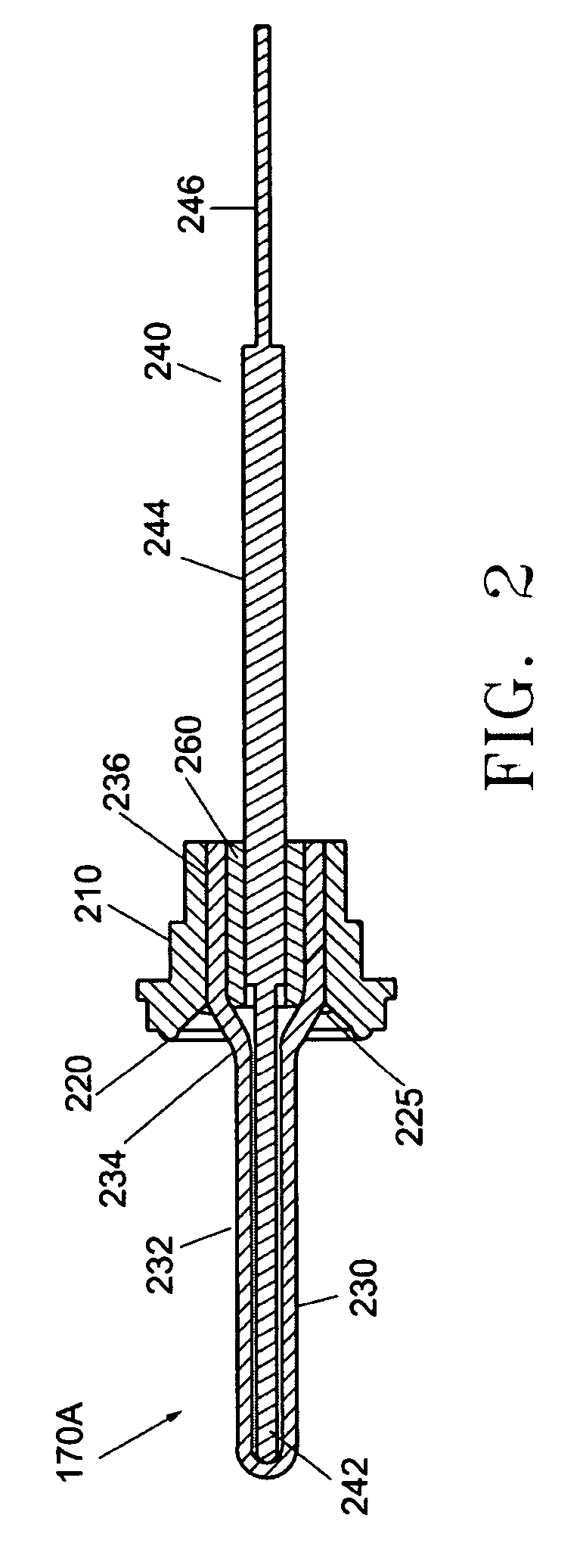
A sensor assembly for accurately measuring the temperature of a process fluid flowing within process tubing is disclosed. A thermocouple sensor can be configured within a protective sheath with leads protruding from the sheath. A gland-like structure can be coupled to the sheath or machined integral to the sheath. The sensor assembly can be coupled to a closed loop. The sensor can be positioned within or in close proximity to the fluid flowing in the closed loop, and the sensor accurately measures the temperature of the process fluid flowing in the closed loop. The sensor assembly is easily assembled and / or disassembled allowing the sensor to be maintained.

Description

CROSS-REFERENCE TO RELATED APPLICATIONS[0001]This patent application is related to commonly owned co-pending U.S. patent application Ser. No. 11 / 065,636, filed Feb. 23, 2005, entitled “IMPROVED RINSING STEP IN SUPERCRITICAL PROCESSING”, U.S. patent application Ser. No. 11 / 065,377, filed Feb. 23, 2005, entitled “IMPROVED CLEANING STEP IN SUPERCRITICAL PROCESSING”, U.S. patent application Ser. No. 11 / 065,376, filed Feb. 23, 2005, entitled “ETCHING AND CLEANING BPSG MATERIAL USING SUPERCR1TICAL PROCESSING”, and U.S. patent application Ser. No. 11 / 091,976, filed Mar. 28, 2005, entitled “HIGH PRESSURE FOURIER TRANSFORM INFRARED CELL”, which are hereby incorporated by reference in its entirety.FIELD OF THE INVENTION[0002]This invention relates to a sensor assembly for measuring the temperature of a fluid. This invention is particularly suited for use in accurately measuring the temperature of process fluids confined to process tubing such as supercritical fluids.BACKGROUND OF THE INVENTIO...

Claims


Application Information

Patent Timeline
Patent Type & Authority Patents(United States)
IPC IPC(8): G01K13/00G01K1/08
CPCG01K1/08G01K1/16G01K13/02
Inventor WUESTER, CHRISTOPHER D.
Owner TOKYO ELECTRON LTD
Learn More