
Method and device for identifying and localizing a fire

a fire and localization technology, applied in the direction of fire alarms, instruments, fire alarm radiation actuation, etc., can solve the problems of difficult firefighting crews to localize the source of fire in large halls, office buildings, complex implementation of one or more suction pipe systems, etc., to achieve the effect of simple and economical

Active Publication Date: 2008-05-20
WAGNER GROUP
View PDF16 Cites 24 Cited by
  • Summary
  • Abstract
  • Description
  • Claims
  • Application Information

AI Technical Summary

Benefits of technology

[0014]One task addressed by the present invention is to provide a simple and economical device and a method for detecting sources of fire which combines the advantages of known smoke and gas suction systems—active intake and concealed mounting—with the advantage of localizing each individual suction opening and thus detecting an actual seat of fire or actual gaseous impurity as occurs when a fire develops. A further task addressed by the present invention consists of providing a fire-extinguishing system comprising an aspirative fire detection device which affords both reliable fire detection as well as localization of the site of a fire from a plurality of monitored areas, whereby the fire detection device can dispense with the need for a plurality of suction pipe systems connecting the individual monitored areas to one sensor in order to detect a fire parameter.

Problems solved by technology

Methods and devices using a plurality of suction pipe systems to detect and localize sources of fire in one or more monitored areas are known from the prior art and have been developed based on the fact that, for example, it is very difficult for firefighting crews to localize the source of a fire in large halls, office buildings, hotels or ships.
Yet when monitoring a plurality of monitored areas, this has the disadvantage that the corresponding number of suction pipe systems must be in place, which involves a very complex implementation of the one or more aspirative fire detection system(s) both structurally as well as financially.
Yet disadvantageous to this construction is that because of their size, design and price, these alarm boxes cannot be employed at each individual air intake opening.
A disadvantage to this known device, however, is the very substantial installation outlay for the matrix-like system of pipes.
Likewise disadvantageous is the high cost of installing the necessary suction lines.
Here as well, the disadvantage to this known device lies in the high installation outlay for the system of pipes.
This device known from the prior art has the disadvantage that due to the number of sub-sensors employed, the costs associated with the fire detecting device are relatively high and furthermore necessitates a relatively complex wiring of the sub-sensors when installing the device.

Method used


Image

  • Method and device for identifying and localizing a fire
  • Method and device for identifying and localizing a fire
  • Method and device for identifying and localizing a fire

Examples


Embodiment Construction

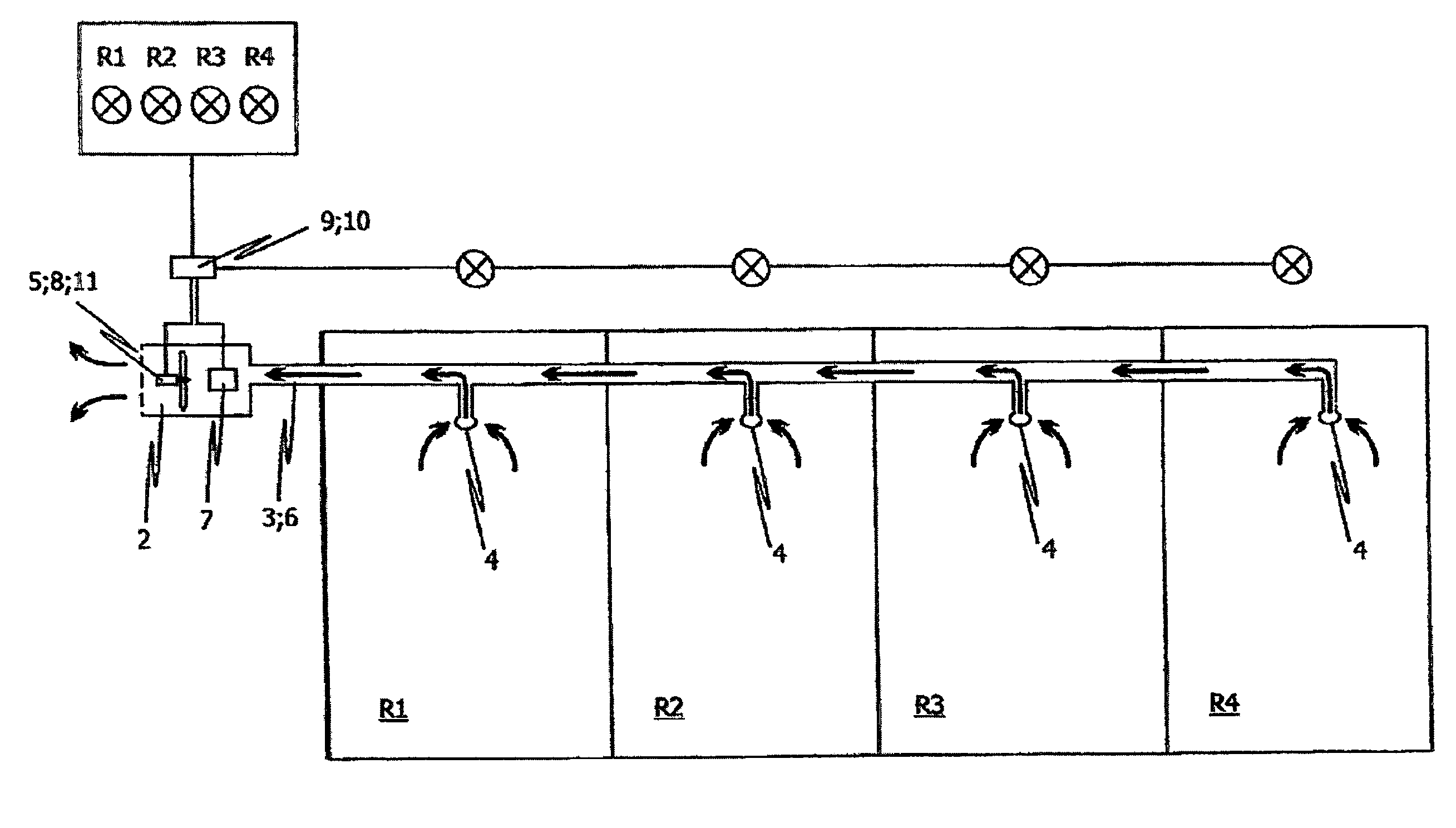
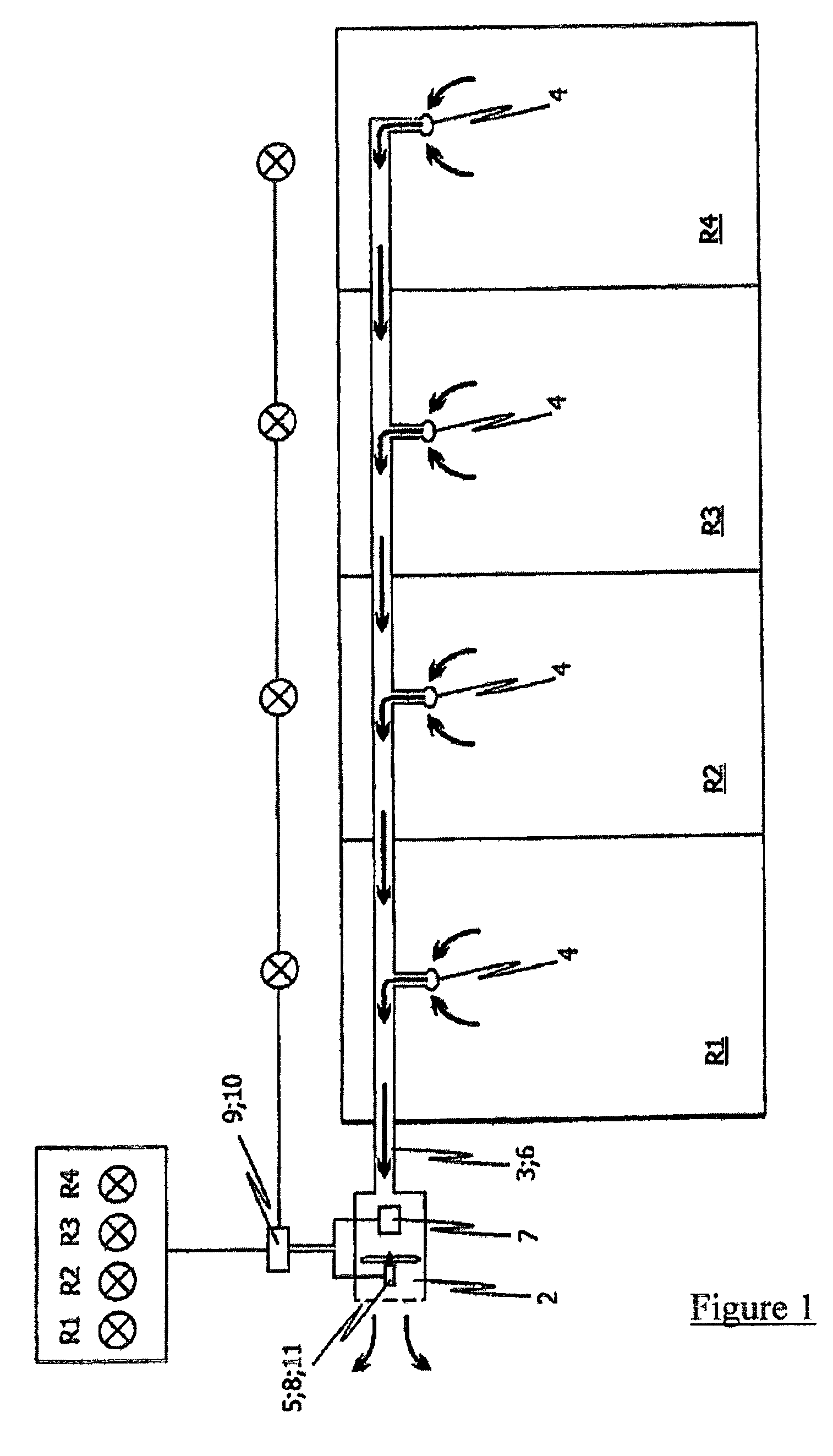
[0045]FIG. 1 is a schematic representation of a preferred embodiment of the inventive device for detecting a fire and for localizing the fire within one monitored area (R1, R2, . . . , Rn) from a plurality of monitored areas (R1, R2, . . . , Rn). The inventive device according to FIG. 1 involves a centrally-arranged, aspirating fire detection device able to precisely localize the site of a fire. In the embodiment as depicted, the device is used to monitor four separate monitored areas (R1, R2, R3, R4). It is hereby provided for each one air sample (6), representative of the room air of the respective monitored areas (R1, . . . , R4) to be continuously extracted from the respective monitored areas (R1, . . . , R4) through a common suction pipe system (3). To this end, a suction device (5) configured as a blower is provided at one end of the suction pipe system (3). The air samples (6) extracted through the common suction pipe system (3) by the suction device (5) are conveyed to a sen...


PUM


Abstract

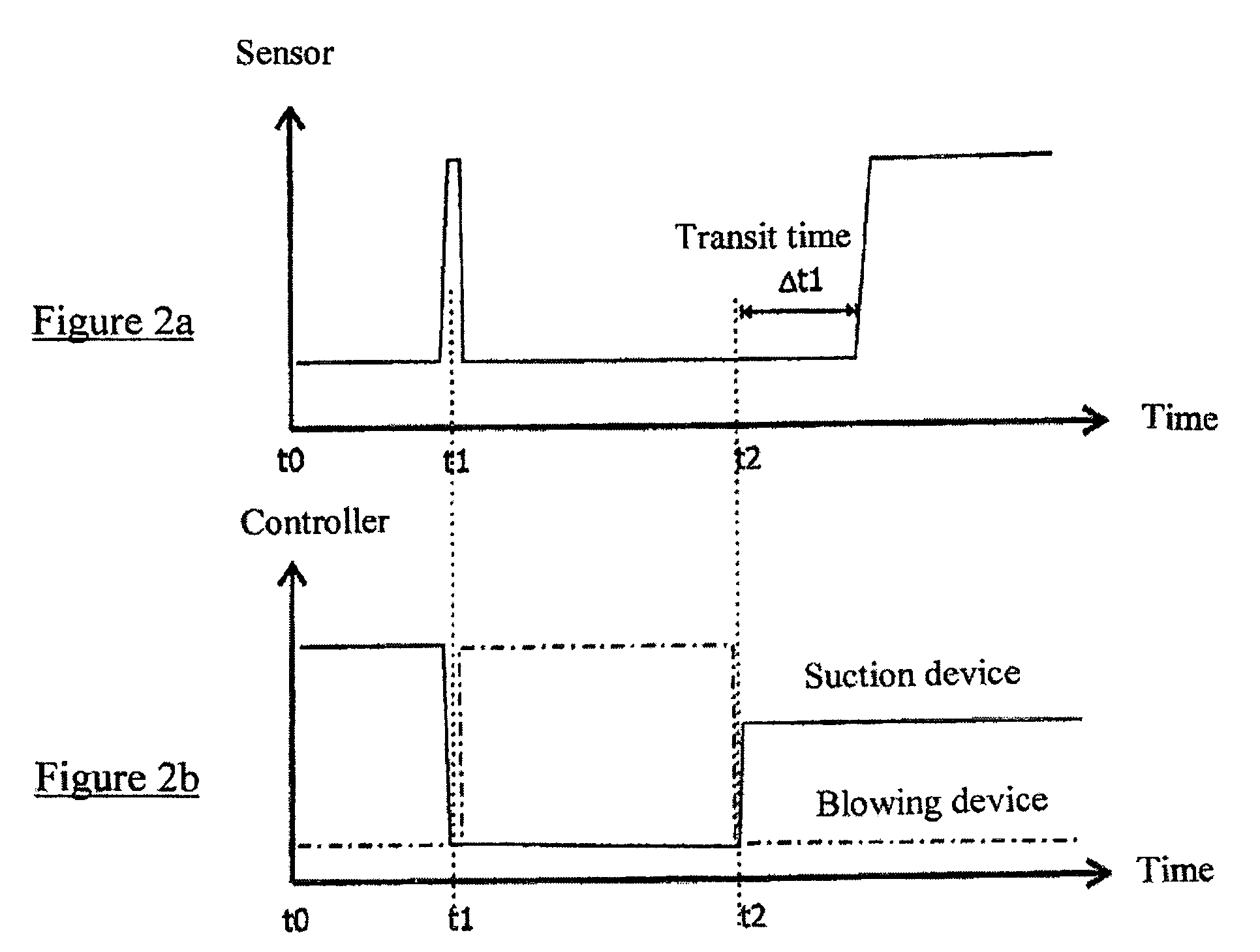
The invention relates to a method and a device for detecting and localizing sources of fire in one or more monitored areas (R1, . . . , Rn) utilizing a suction pipe system (3) connecting the plurality of monitored areas (R1, . . . , Rn) and which communicates with each individual monitored area (R1, . . . , Rn) by means of at least one suction opening (4), a suction device (5) for extracting air samples (6) representative of the room air of the individual monitored areas (R1, . . . , Rn) from the individual monitored areas (R1, . . . , Rn) by means of the suction pipe system (3) and the suction openings (4), and a sensor (7) for detecting at least one fire parameter in the air samples (6) extracted through the suction pipe system (3), whereby the inventive device comprises a blowing device (8) for blowing out the air samples (6) suctioned into the suction pipe system (3) when sensor (7) detects at least one fire parameter in the extracted air samples (6). The fire is localized by means of the transit time measurement of a re-extracted fire parameter.

Description

BACKGROUND OF THE INVENTION[0001]1. Field of the Invention[0002]The invention relates to a method for detecting and localizing a fire and / or the origin of a fire in one or more monitored areas as well as a device for realizing the method.[0003]The invention starts out from a fire detecting device having a sensor for detecting a fire parameter which is fed a representative volume of room or device air through a suction pipe system by means of a suction device such as a fan.[0004]2. Description of Related Art[0005]The term “fire parameter” is to be understood as physical variables which are subject to measurable changes in the vicinity of an incipient fire, e.g. ambient temperature, solid or liquid or gaseous content in the ambient air (accumulation of smoke particles or particulate matter or accumulating smoke or gases) or local background radiation.[0006]Both procedures as well as fire detecting devices of the cited type are known and serve for prompt detecting of fires still in the...

Claims


Application Information

Patent Timeline
IPC IPC(8): G08B17/10G01N1/16
CPCG08B17/10
Inventor SIEMENS, ANDREASREINECKE, CLAUS-PETER
Owner WAGNER GROUP
Learn More