
Waterproof, miniature light-emitting diode (LED) device

a technology of miniature led devices and light-emitting diodes, which is applied in the direction of semiconductor devices for light sources, light-emitting devices, nibs, etc., can solve the problems of inability to use miniature led devices, water entering the space between the opposing edges of the axial parts, and the inability to prevent inadvertent movement of led devices, so as to prevent inadvertent change of on or off status of devices, the effect of reliably maintaining the status

Inactive Publication Date: 2008-05-20
PNC BANK NAT ASSOC
View PDF24 Cites 7 Cited by
  • Summary
  • Abstract
  • Description
  • Claims
  • Application Information

AI Technical Summary

Benefits of technology

"The present invention provides a new and improved miniature LED device that is waterproof. The device allows for two axial parts to be rotatable relative to one another to control illumination while preventing water from entering the space between the parts. The device can be maintained in its set position without accidental rotation. The device includes a cylinder with a chamber for batteries, an LED light assembly, and a dome connected to the cylinder. The device is controlled by rotating the housing parts relative to each other to form or interrupt the electrical circuit. An elastic ring or similar structure prevents water from entering the cylinder and interrupting the electrical circuit. The device provides better light distribution with a faceted dome."

Problems solved by technology

A particular problem with such miniature LED devices is that when the LED devices are exposed to water, the water can enter into the space between the opposed edges of the axial parts.
From this space, the water can seep between the threads into the interior of the LED device and interrupt the circuit between the LED and the batteries, i.e., cause a short-circuit.
Once this happens, the LED device is rendered useless.
In view of this problem, such miniature LED devices are often not used in environments in which water is likely to be present.
Another problem with such miniature LED devices is that one of the axial parts might be inadvertently rotated relative to the other thereby turning the LED on or off when set in either position, i.e., the inadvertent rotation might turn the LED off when the device is set in the on position or turn the LED on when the device is set in the off position.

Method used


Image

  • Waterproof, miniature light-emitting diode (LED) device
  • Waterproof, miniature light-emitting diode (LED) device

Examples


Embodiment Construction

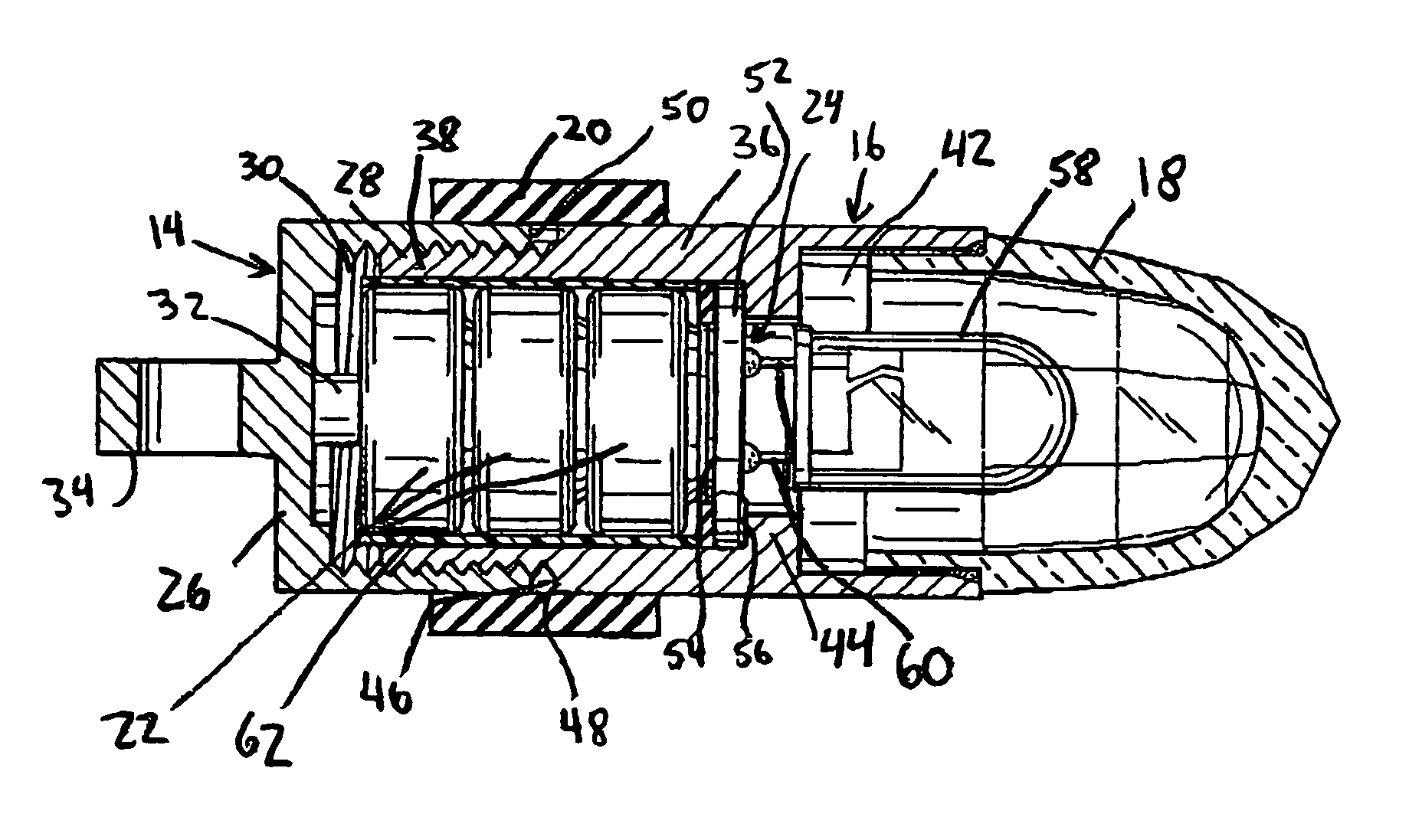
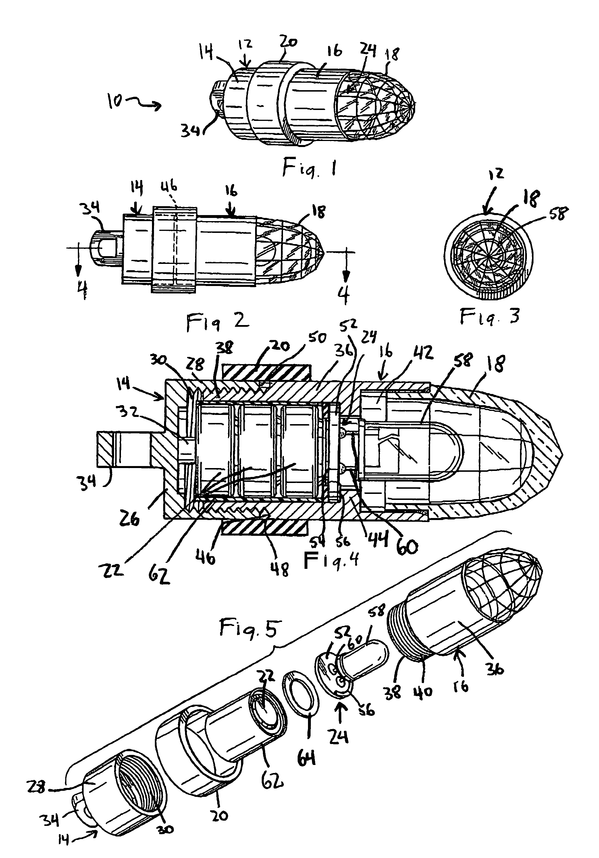
[0020]Referring to the accompanying drawings wherein like reference numerals refer to the same or similar elements, a miniature LED device 10 in accordance with the invention includes a cylinder 12 having a bottom housing part 14 and a top housing 16, a faceted dome 18 coupled to the top housing part 16, an elastic ring 20 arranged around the cylinder 12, batteries 22 housed in a chamber defined in the cylinder 12 and an LED light assembly 24 arranged in connection with the cylinder 12. In the convention used herein, the bottom of the device 10 is considered the leftmost part of the device 10 as shown in the drawings whereas the top of the device 10 is considered the rightmost part of the device 10 as shown in the drawings.

[0021]Both bottom and top housing parts 14, 16 are made at least partially of an electrically conductive material such as metal to enable completion of an electric circuit including the batteries 22 and the LED light assembly 24. Additional details of the formatio...


PUM


Abstract

Waterproof miniature LED device including a cylinder having a first housing part with an internal thread and a second housing part with an external thread and rotatably coupled to the first housing part via engagement of the threads, an LED light assembly mounted to the cylinder and a dome connected to the cylinder and covering the LED light assembly. The cylinder defines a chamber for receiving batteries. Each housing part is conductive to enable formation of an electrical circuit including the batteries, LED light assembly and conductive portions of the housing parts. Illumination provided by the LED light assembly is controlled by rotating the housing parts relative to one another causing formation or interruption of the electrical circuit. An elastic ring covers a space between the housing parts alongside the threads to prevent water from entering between the threads into the interior of the cylinder and interrupting the electrical circuit.

Description

FIELD OF THE INVENTION[0001]The present invention relates generally to a miniature light-emitting diode (LED) device and more specifically to a miniature LED-light emitting device which is waterproof and therefore can be used in environments in which it will be exposed to water.BACKGROUND OF THE INVENTION[0002]A typical miniature LED device includes a metal cylinder in which an LED and batteries for providing power thereto are received. The cylinder includes opposite axial parts whereby one axial part has a tubular part with an internal thread while the other axial part has a smaller diameter tubular part with an external thread engageable with the internal thread, with the cooperating threads allowing relative rotation between the axial parts. Illumination of the LED is controlled by rotating one axial part of the metal cylinder relative to the other axial part which regulates the formation or interruption of a circuit between the LED and the batteries.[0003]To enable the relative ...

Claims


Application Information

Patent Timeline
Patent Type & Authority Patents(United States)
IPC IPC(8): F21L4/00
CPCF21L4/04F21V23/0414F21V31/00F21Y2101/02Y10S362/80F21Y2115/10
Inventor CUTLER-BASS, JUDY
Owner PNC BANK NAT ASSOC
Learn More