
Circulation type media agitator mill

a agitator mill and media technology, applied in the field of circular media agitator mills, can solve the problems of preventing the even application of crushing power, abnormal heat generation or wear, and restricting the use of materials, so as to achieve the effect of reducing the risk of crushing

Inactive Publication Date: 2008-05-20
ASHIZAWA FINETECH
View PDF12 Cites 15 Cited by
  • Summary
  • Abstract
  • Description
  • Claims
  • Application Information

AI Technical Summary

Benefits of technology

The present invention relates to a circulation type media agitator mill that can improve the crushing power and the mobility of grinding media, as well as enhance the crushing efficiency and media separating efficiency. This allows the mill to work at high rotating speeds. The mill includes a cylindrical vessel, an agitating member, a media-separating member, an inlet, an outlet, and a circulation passage. The agitating member has a cylindrical wall and a hub, and the grinding media is contained in the grinding chamber defined between the cylindrical wall of the agitating member and a surrounding cylindrical wall of the vessel. The media-separating member is a cylindrical screen or a vaned wheel. The invention also includes a design for the vessel that allows for even distribution of the grinding media and prevents the media from deviating towards the shaft of the agitating member. The grinding media can be selectively separated using a screening cylinder or a centrifugal vaned wheel based on its viscosity. The baffles on the inner wall surface of the vessel prevent the media from slipping and improve the crushing efficiency.

Problems solved by technology

These materials, however, should not be understood as restrictive.
This provides some disadvantages: if the material to be ground is high in viscosity, or if the bead-like grinding media is of relatively small sized pieces, the grinding media is apt to be driven toward the outlet, thereby preventing the even application of the crushing power to the “to be ground” material while being rubbed, and abnormal heat generation or wearing is caused.
Sometimes, the mill may be overloaded in operation until it stalls.
This problem grows noticeable more and more as the bead-like grinding media reduces less and less in particle size.
In the hope of preventing appearance of short cuts and making full use of the rotary energy it has been proposed that an annular space around the grinding vessel is used as the grinding chamber, but the problem of the grinding media being localized remains unsolved.

Method used


Image

  • Circulation type media agitator mill
  • Circulation type media agitator mill
  • Circulation type media agitator mill

Examples


Embodiment Construction

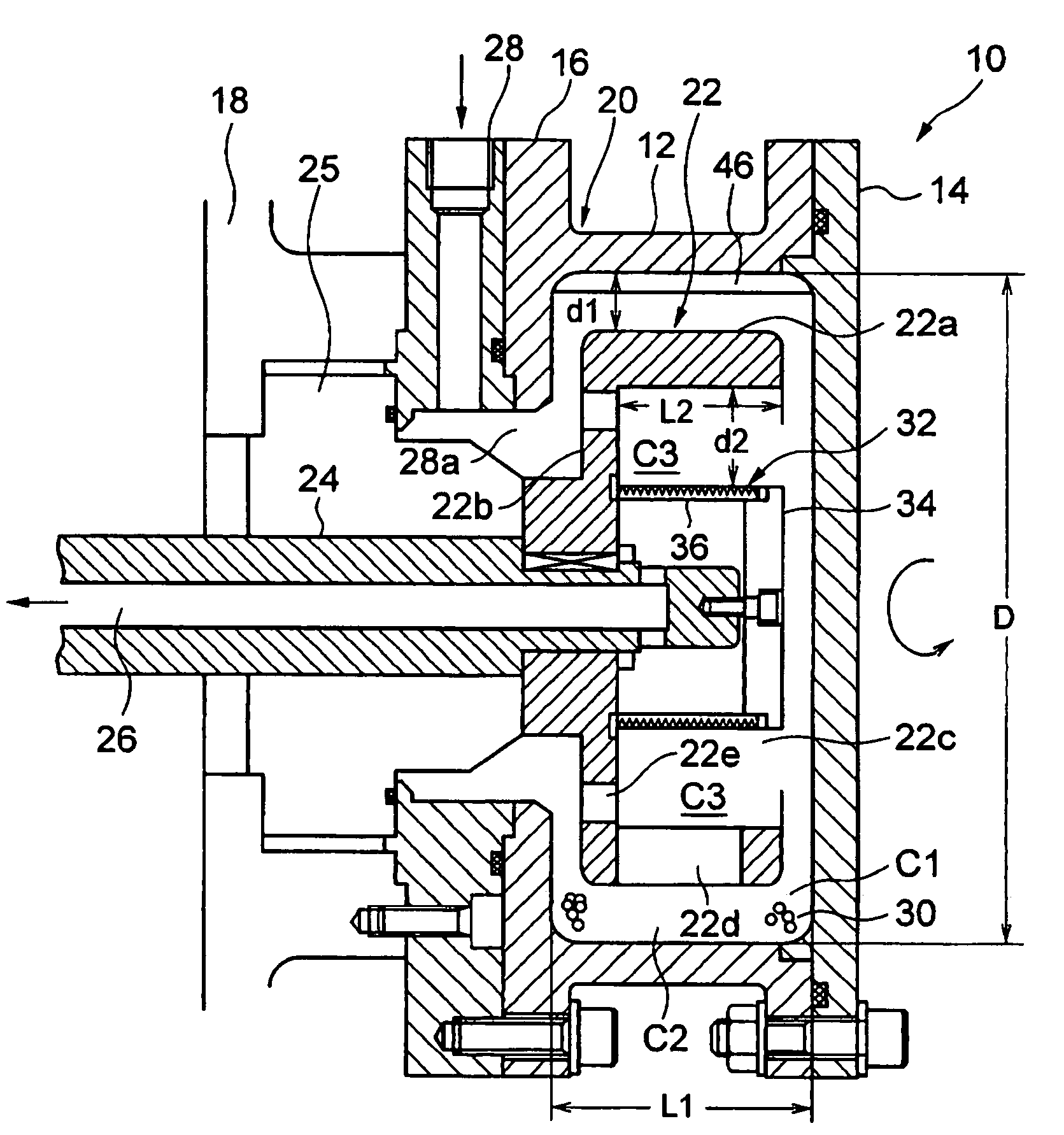
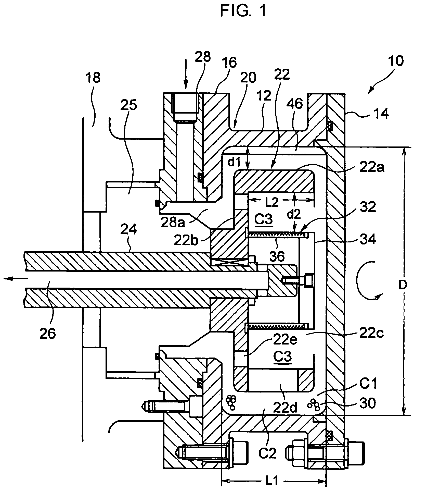
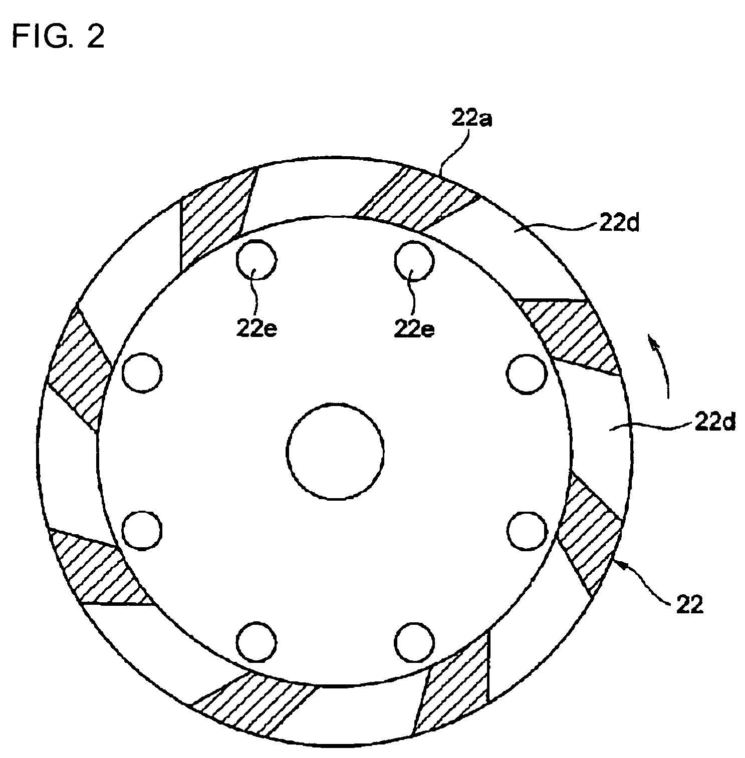
[0025]Referring to FIG. 1, a circulation type media agitator mill or slurry-circulating and grinding media-agitating type of agitator mill 10 according to the first embodiment of the present invention includes a vessel 20 comprising a cylindrical barrel 12, an end plate 14 fixed to one end of the barrel 12, an inlet flange 16 fixed to the other end of the barrel 12 and a frame 18 fixed through the inlet flange 16. The vessel 20 defines a hermetically sealed vessel chamber C1 inside, whose lateral length-to-diameter ratio (L1 / D) is smaller than one, preferably in the 0.3 to 0.4 range. For the lateral length-to-diameter ratio larger than one (L1 / D>1) the bead-like grinding media is liable to cohere in the axial direction, thereby causing unusual wearing or heat generation in the barrel 12. For the lateral length-to-diameter ratio smaller than one (L1 / D<1) the bead-like grinding media can be kept dispersive while moving.

[0026]A rotary agitating member 22 is rotatably mounted in the bar...


PUM


Abstract

A circulation type media agitator mill includes a cylindrical vessel, and an agitating member arranged rotatably in the cylindrical vessel. A grinding media is contained in a grinding chamber defined between a cylindrical wall of the agitating member and a surrounding cylindrical wall of the vessel. A media-separating member is arranged coaxial with the agitating member in the inner space of the agitating member. An inlet is provided for leading material to be ground to the grinding chamber, and an outlet leads the material separated from the grinding media to the outside of the mill via the media separating member. The vessel may have a length to diameter ratio smaller than one. The cylindrical wall and hub of the agitatihg member have openings to allow the grinding chamber to communicate with the media separating chamber.

Description

BACKGROUND OF THE INVENTION[0001]The present invention relates to a circulation type media agitator mill. The circulation type media agitator mill in accordance with this invention is appropriate for grinding or dispersing into powder a variety of small pieces of material such as ink, paint, dying material, ceramic material, metal, inorganic material, ferrite, toner, glass or pigmented paper-coating material. These materials, however, should not be understood as restrictive.[0002]Japanese Patent Publication No. H 02-10699 shows a conventional mill of the type which has being in practical use. It comprises: a mill body which includes a grinding chamber to be filled at least partly with grinding media and material to be ground and has an inlet for material to be ground and an outlet for crushed material, an agitator shaft having an inner shaft end inside the grinding chamber, and a separating means permitting finished pulverized material to flow out of the grinding chamber to the outl...

Claims


Application Information

Patent Timeline
Patent Type & Authority Patents(United States)
IPC IPC(8): B02C17/16
CPCB02C17/161B02C17/16B02C19/00
Inventor ISHIKAWA, TSUYOSHIIIOKA, MASAKATSUISHII, TOSHIHIROHARIGAI, KAORI
Owner ASHIZAWA FINETECH
Learn More