
ZIF connection accessory and ZIF browser for an electronic probe

a technology of electronic probes and accessories, applied in the direction of coupling contact members, coupling device connections, engagement/disengagement of coupling parts, etc., can solve the problems of difficult to meet the needs of users of certain types of electronic test equipment, such as oscilloscopes and logic analyzers, and the difficulty of adjusting the settings,

Inactive Publication Date: 2008-05-13
AGILENT TECH INC
View PDF8 Cites 8 Cited by
  • Summary
  • Abstract
  • Description
  • Claims
  • Application Information

AI Technical Summary

Benefits of technology

The ZIF browser system enhances the robustness and longevity of connections, allowing for multiple uses without frequent replacement, reducing the risk of damage to the probe and PCB, and simplifies the handling and maneuvering of flexible leads, thereby improving the reliability and efficiency of signal probing operations.

Problems solved by technology

Users of certain types of electronic test equipment, such as oscilloscopes and logic analyzers are frequently faced with a dilemma.
The connection to the DUT (Device Under Test) or SUT (System Under Test) must be made through a probe of some sort, but there is almost no room to allow it.
These are expensive and delicate assemblies that generally have a ‘probe pod’ that connects to the front panel of the 'scope, while a cable carries power and a transmission line for the signal from the probe pod to a small handheld probe housing that encloses an amplifier that can drive the transmission line.
This works, but gets to be a major aggravation mighty fast if there are many different locations to be observed during the analysis of some complicated situation.
ZIF connectors are commonly used in situations where there are many pins (e.g., a large microprocessor that is to be replaceable in the field) and the cost and likelihood of damage using a standard connector is a prohibitive risk.
Even with good alignment there is still the issue of damage to the PCB or cracking the substrate of the part.
Then there is the issue of how to get the old part out.
In the case of SIGNAL PROBE AND PROBE ASSEMBLY the issue is not so much the number of pins, but the mechanical delicateness of the probe tip and the lack of strength in the solder joints used to affix the flying leads to the PCB.
Bending over in bad light, hands extended beyond the focus of your glasses, off balance and standing on one foot, it is all too easy to accidently apply too much force to a regular connector and break something.
Furthermore, attaching and detaching things to that probe is not a nonchalant operation with no risk; done carelessly (or if a gorilla is on the loose) it can damage the probe.

Method used


Image

  • ZIF connection accessory and ZIF browser for an electronic probe
  • ZIF connection accessory and ZIF browser for an electronic probe
  • ZIF connection accessory and ZIF browser for an electronic probe

Examples


Embodiment Construction

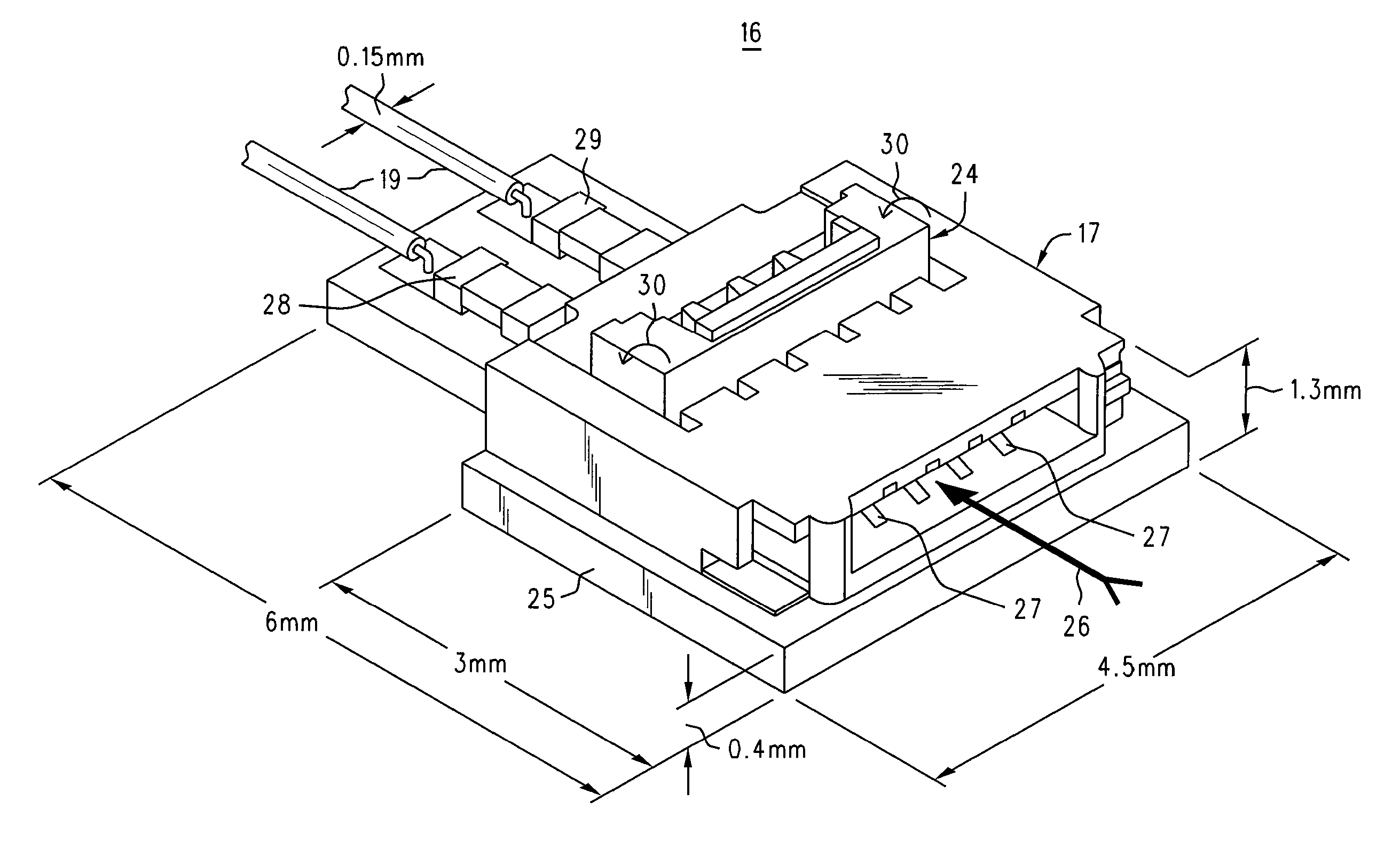
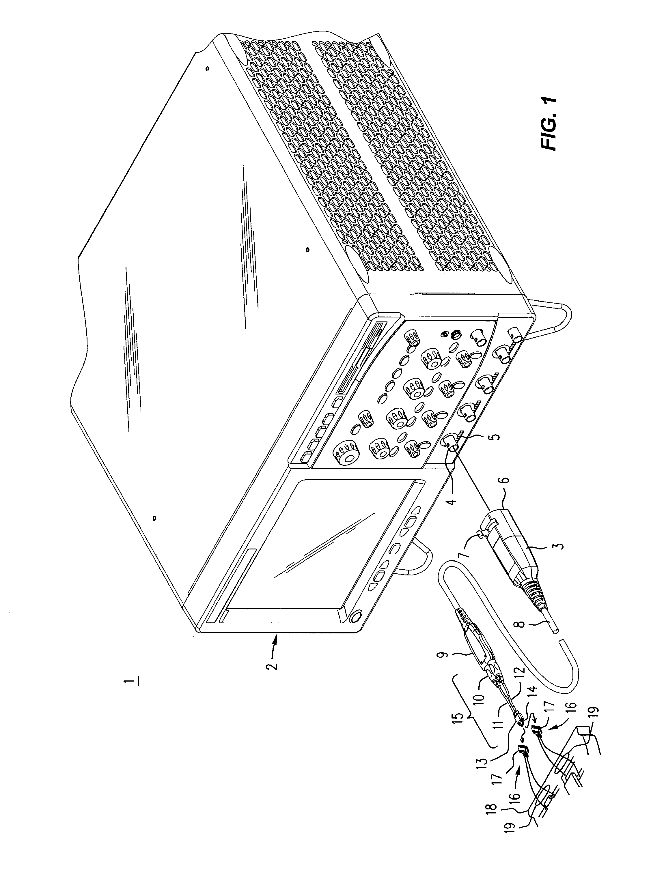
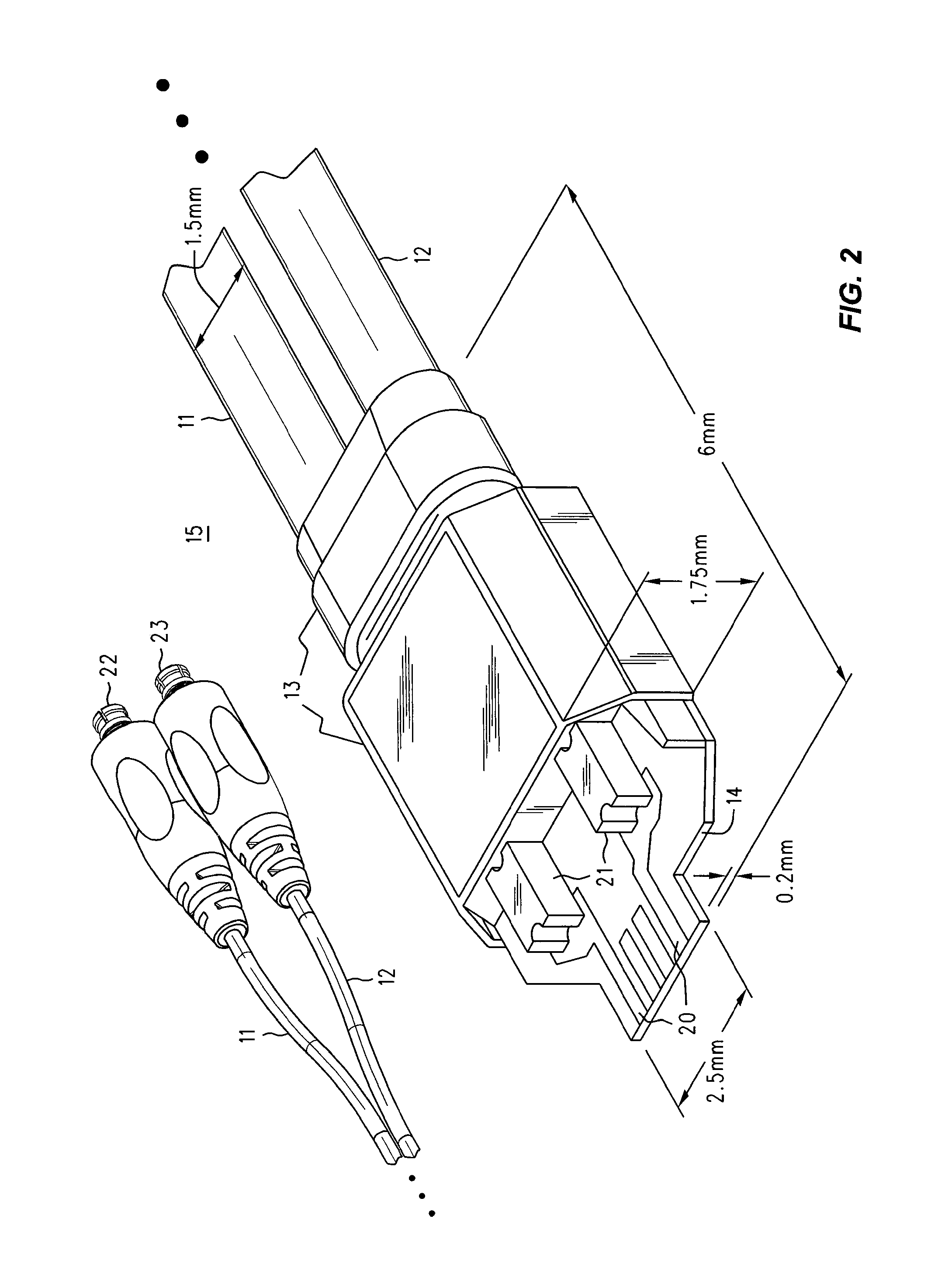
[0013]Refer now to FIG. 1, wherein is shown a front perspective view 1 of an electronic instrument 2, such as a wideband digital oscilloscope, having one or more front panel connectors 4 that each receive a probe pod 3 bearing (in the example) a push-lock BNC connector, say, in support of operation with active probes. In a manner known in the prior art, the probe pod 3 is installed simply by lining it up and then pushing it toward the 'scope. When the probe pod 3 is in place, not only is a BNC connection established to connector 4, a row of spring loaded pins 6 (not visible) on the front panel of the pod assembly engages a row 5 of contacts beneath the connector 4. To remove the push-lock connector the operator pushes on lever or tab 7 with a thumb or a finger, while pulling the assembly away from the 'scope. A main cable 8 carries both power to, and signal information from, a handheld probe housing 9 containing the high frequency replication amplifiers that make the probe an ‘activ...


PUM


Abstract

A ZIF connector is mounted on a tiny PCB that carries damping components and flying leads that are connected or soldered to locations of interest on a PCB. There may be one or many of such ZIF connector / connection accessories in any particular test set-up. A ZIF browser is connected to an active probe's tip by short flexible extended transmission lines that lead back to a small interconnect PCB having plated lands that are inserted into the ZIF connector. The ZIF connector is good for just a limited number of uses, but this is in agreement the a customer's usage model for an inexpensive ‘disposable’ part. Furthermore, the limited lifetime of the ZIF connector / connection accessory is apt to be mitigated in cases where several are in use at one time. The precision microwave connection of the ZIF browser to a potentially delicate and expensive probe tip need not be performed frequently for replacement of the ZIF browser, as the plating on the lands of the interconnect PCB is made thick enough to allow those lands to have a lifetime of 1,500 or more insertions, which is two to three times the amount research suggests is a typical customer expectation.

Description

REFERENCE TO RELATED APPLICATION[0001]This application is related to the subject matter of an earlier filed US patent application entitled SIGNAL PROBE AND PROBE ASSEMBLY, Ser. No. 11 / 227,943, filed 15 Sep. 2005 by Michael T. McTigue and assigned to Agilent Technologies, Inc. Because of the similarity in subject matter, and for the sake of both completeness and brevity, SIGNAL PROBE AND PROBE ASSEMBLY is hereby expressly incorporated herein by reference.INTRODUCTION AND BACKGROUND[0002]Users of certain types of electronic test equipment, such as oscilloscopes and logic analyzers are frequently faced with a dilemma. The connection to the DUT (Device Under Test) or SUT (System Under Test) must be made through a probe of some sort, but there is almost no room to allow it. For example, while one might connect the 50Ω front panel input of a high bandwidth oscilloscope to the 50Ω front panel output of some microwave signal generator using a length of suitable 50Ω transmission line, to get...

Claims


Application Information

Patent Timeline
Patent Type & Authority Patents(United States)
IPC IPC(8): H01R13/15
CPCH01R12/88H01R12/79H01R13/193H01R31/06
Inventor JOHNSON, KENNETH W
Owner AGILENT TECH INC
Learn More