Liquid ejection head having improved durability against liquid, liquid cartridge having such a liquid ejection head, liquid ejection apparatus having such a liquid cartridge, image forming apparatus having such a liquid ejection apparatus, and manufacturing method of liquid ejecting head

a technology of liquid ejection head and durability, which is applied in the direction of printing, etc., can solve the problems of difficult development of such ink that does not cause corrosion difficult to satisfy the durability condition of the material of the liquid ejection head with regard to the liquid, and the inability to produce such ink over a wide range of materials, etc., to achieve the effect of improving the efficiency of liquid ejection, suppressing the inability to ej

Inactive Publication Date: 2008-05-13
RICOH KK
View PDF17 Cites 10 Cited by
  • Summary
  • Abstract
  • Description
  • Claims
  • Application Information

AI Technical Summary

Benefits of technology

[0016]Thus, it is important with such an ink-jet head to develop the material of the liquid ejection head that is resistant against corrosion caused by the ink, or to find out the ink composition that does not cause corrosion in the ink ejection head. However, development of such ink that does not cause corrosion over wide spectrum of materials is a difficult task. In addition to the foregoing, the ink for an ink-jet recording apparatus is required, in order to achieve high quality image recording, to satisfy the demand with regard to the durability for the recording medium on which the recording is made with the ink and further to satisfy the demand of durability for the material of the plural layers constituting the movable member that makes a contact with the ink.
[0021]The present invention has been made in view of the foregoing problems and has its object of providing a liquid ejection head in which the degree of freedom for the selection of the liquid used with the head is increased or in which the degree of freedom for the selection of the material forming the movable member used in the head is increased. Further, the present invention provides a liquid ejection head in which instability of ejecting characteristics or defective ejecting is suppressed and the quality of the pattern formed on a medium is improved. In addition, the present invention provides a liquid ejection head in which the efficiency of liquid ejection is improved. Further, the present invention provides a liquid cartridge, liquid electing apparatus and image forming apparatus, and manufacturing method of a liquid ejection head.

Problems solved by technology

In the art of ink-jet recording apparatus, it is generally practiced to use an alkaline ink for the ink to be ejected, while the use of such alkaline ink leads to the problem that the material contacting with the ink tends to undergo corrosion.
However, development of such ink that does not cause corrosion over wide spectrum of materials is a difficult task.
Further, in the case a liquid other than ink is used for the liquid with such liquid ejection head, as in the case of fabricating DNA chips, formation of metal interconnections, formation of color filters, or the like, various solvents are used with the liquid, and it becomes extremely difficult to satisfy the condition of durability for the material of the liquid ejection head with regard to the liquid used therewith.
Further, in the case there is formed the foregoing sawtooth part at the free edge part of the movable member, there is inevitably formed a part of extremely reduced thickness (the part formed of only one layer) in such a structure, while such a part of reduced thickness easily undergoes cracking or chipping with the mechanical shock associated with formation or annihilation of bubbles.
Thereby, there may be caused problems such as unstable ejection of the liquid droplets between different channels or choking or clogging of the liquid ejecting port or the liquid passage caused by the chipped fragments.
Any of these can result in deterioration of the printing quality.

Method used


Image

  • Liquid ejection head having improved durability against liquid, liquid cartridge having such a liquid ejection head, liquid ejection apparatus having such a liquid cartridge, image forming apparatus having such a liquid ejection apparatus, and manufacturing method of liquid ejecting head
  • Liquid ejection head having improved durability against liquid, liquid cartridge having such a liquid ejection head, liquid ejection apparatus having such a liquid cartridge, image forming apparatus having such a liquid ejection apparatus, and manufacturing method of liquid ejecting head
  • Liquid ejection head having improved durability against liquid, liquid cartridge having such a liquid ejection head, liquid ejection apparatus having such a liquid cartridge, image forming apparatus having such a liquid ejection apparatus, and manufacturing method of liquid ejecting head

Examples


first embodiment

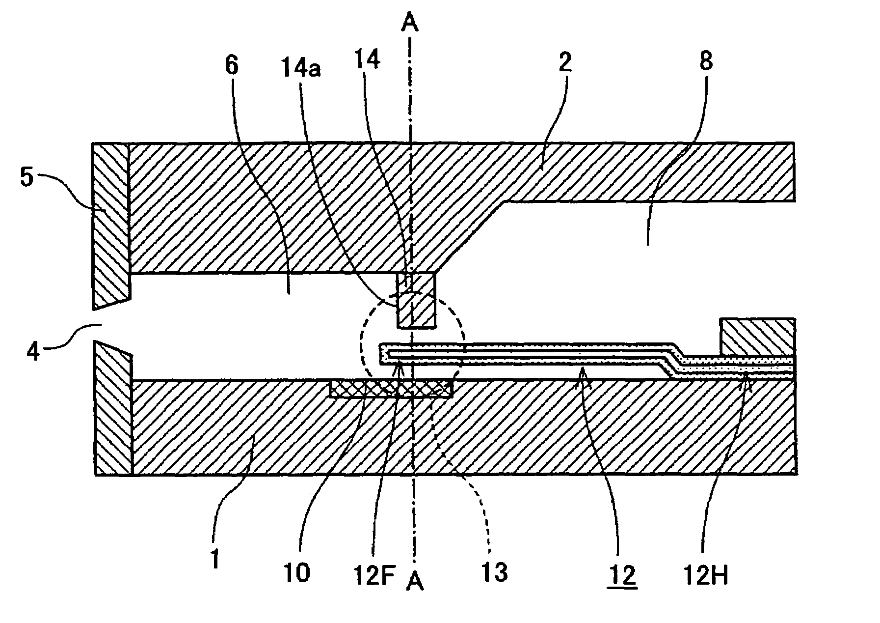
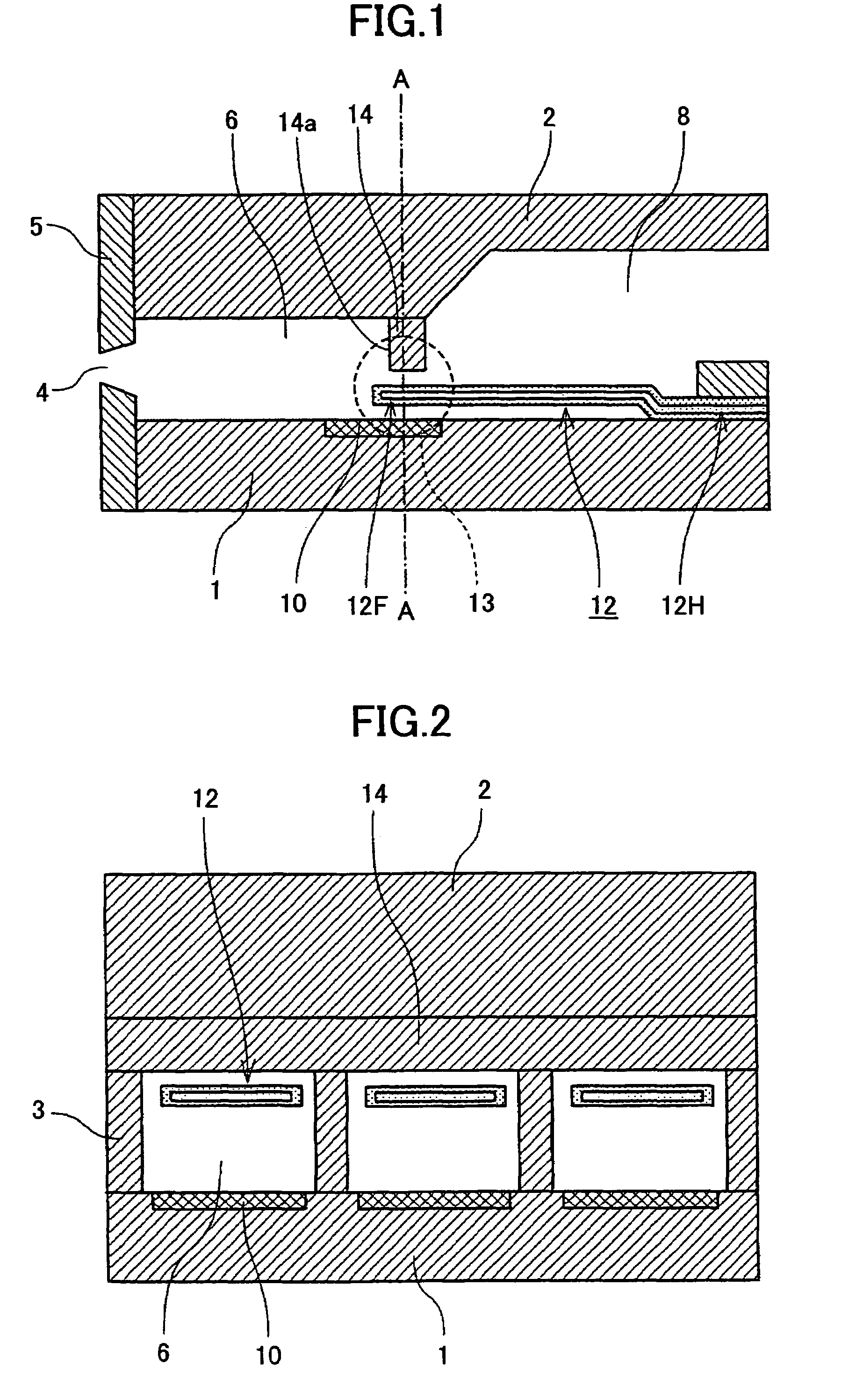
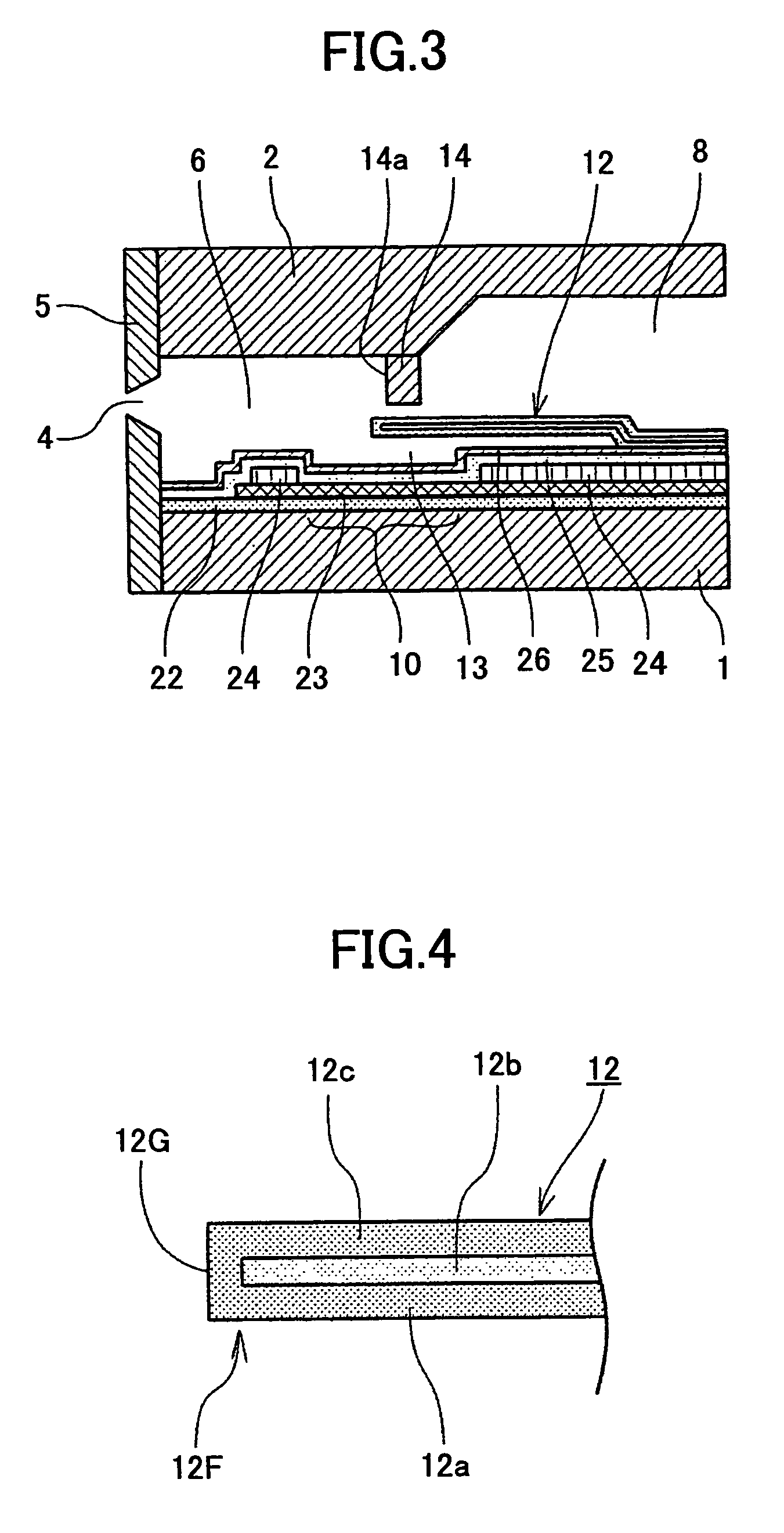
[0050]First, a first embodiment of the liquid ejection head of the present invention will be described with reference to FIGS. 1-3, wherein it should be noted that FIG. 1 is a cross-sectional diagram of the liquid ejection head, while FIG. 2 is a cross-sectional diagram taken along A-A line of FIG. 1. FIG. 3 is a cross-sectional diagram showing an example of the device substrate of the liquid ejection head, while FIG. 4 is an enlarged view diagram of a movable member of the head.

[0051]Referring to the drawings, the liquid ejection head includes a device substrate 1 and a top plate 2 forming therebetween a plurality of flow passages 6 such that the flow passages 6 are separated from each other by separation walls 3. Each of the flow passages 6 communicates with a corresponding ejection port 4 formed in a nozzle plate 5 directly, wherein the foregoing plural flow passages 6 are communicated with a common liquid supply chamber 8 of large volume formed between the device substrate 1 and...

second embodiment

[0099]Next, a second embodiment of the present invention will be described with reference to FIG. 7, wherein it should be noted that FIG. 7 explains a movable member 42 according to the second embodiment of the present invention in detail.

[0100]Referring to FIG. 7, it will be noted that the movable member 42 of the present embodiment has a three-layer structure in which there are laminated three layers of three, different materials for forming the movable member 42, contrary to the case of the movable member 12 of the first embodiment, in which three layers 12a, 12b and 12c of two different materials are laminated (layers 12a and 12c are formed of a first material and the layer 12b is formed of a second material).

[0101]Thus, the movable member 42 is formed of consecutive lamination of the first layer 42a, the second layer 42b and the third layer 42c from the side of the device substrate 1, wherein these first through third layers 42a-42c are formed of respective, different materials...

third embodiment

[0105]Next, a third embodiment of the present invention will be described with reference to FIG. 8, wherein it should be noted that FIG. 8 is a cross-sectional diagram explaining a movable member 52 according to the third embodiment.

[0106]It should be noted that the movable body 52 used with the present embodiment has a construction in which two layers of different materials are laminated to form a five-layer structure.

[0107]Thus, the movable member 52 is formed by laminating a first layer 52a, a second layer 52b, a third layer 52c, a fourth layer 52d and a fifth layer 52e consecutively on the device substrate 1, wherein the first layer 52a, the third layer 52c and the fifth layer 52e are formed of the same material, while the second layer 52b and the fourth layer 52d are formed of the same material different from the material forming the layers 52a, 52c and 52e. Thereby, it should be noted that the respective edge surfaces of the second layer 52b and the fourth layer 52d at the fre...


PUM


Abstract

A liquid ejection head includes therein a movable member, wherein the movable member is formed of lamination of at least three layers, at least one layer thereof having a free edge part covered with another layer.

Description

TECHNICAL FIELD[0001]The present invention relates to a liquid ejection head, liquid cartridge, liquid ejection apparatus and image forming apparatus, and manufacturing method of a liquid electing head.BACKGROUND ART[0002]An ink-jet recording apparatus includes a liquid ejection apparatus that uses a liquid ejection head for an ink-jet recording head. An ink-jet recording apparatus has been used extensively as an image forming apparatus of printers, facsimile machines, copiers or compound machines of these. Here, it should be noted that an ink-jet recording apparatus is defined as an apparatus that records images on a sheet (not limited to paper but includes also OHP sheet or any other medium on which ink droplets or other liquids can be attached and is called also as recording medium, recorded medium or recording sheet) by way of an ink recording head. Thereby, an ink-jet recording apparatus is capable of recording high-definition color images on such a medium with high speed.[0003...

Claims


Application Information

Patent Timeline
Patent Type & Authority Patents(United States)
IPC IPC(8): B41J2/04B41J2/05B41J2/14B41J2/16
CPCB41J2/14048B41J2/1604B41J2/1626B41J2/1631B41J2/1639B41J2/1642B41J2/1601
Inventor HASHIMOTO, KENICHIROH
Owner RICOH KK
Why Eureka
Try Eureka