
Extendable conveyor with boom brake

a technology of boom brake and extension belt, which is applied in mechanical conveyors, loading/unloading, transportation and packaging, etc., can solve the problems of limiting the relative movement of the extendable unit or unit, and achieve the effect of convenient extension and retractability, and optimal extension ra

Active Publication Date: 2008-05-13
KÖRBER SUPPLY CHAIN LLC
View PDF23 Cites 21 Cited by
  • Summary
  • Abstract
  • Description
  • Claims
  • Application Information

AI Technical Summary

Benefits of technology

[0008]The braking element may engage a support roller or the like of one of the extendable units or the base, whereby the braking element may limit rotation of the support roller when so engaged, thereby limiting relative movement of the extendable unit or units. The braking device may include a biasing element that biases or urges the braking element into engagement with the support roller when the braking device is deactivated or de-energized.
[0011]Therefore, the present invention provides a cantilevered extendable conveyor or loader which provides optimal extension rates and package travel rates, while providing clearance of obstacles within the truck trailer. The extendable units are fully nested and may be readily extended and retracted via an electromechanical extension / retraction device. Extension of the extendable units is automatically limited or substantially precluded when such extension is not desired or elected by an operator. The braking device of the present invention thus provides a substantially fail-safe braking device for limiting movement of the extendable conveyor unit in situations where extension or retraction of the extendable conveyor unit is not desired.

Problems solved by technology

The braking element may engage a support roller or the like of one of the extendable units or the base, whereby the braking element may limit rotation of the support roller when so engaged, thereby limiting relative movement of the extendable unit or units.

Method used


Image

  • Extendable conveyor with boom brake
  • Extendable conveyor with boom brake
  • Extendable conveyor with boom brake

Examples


Embodiment Construction

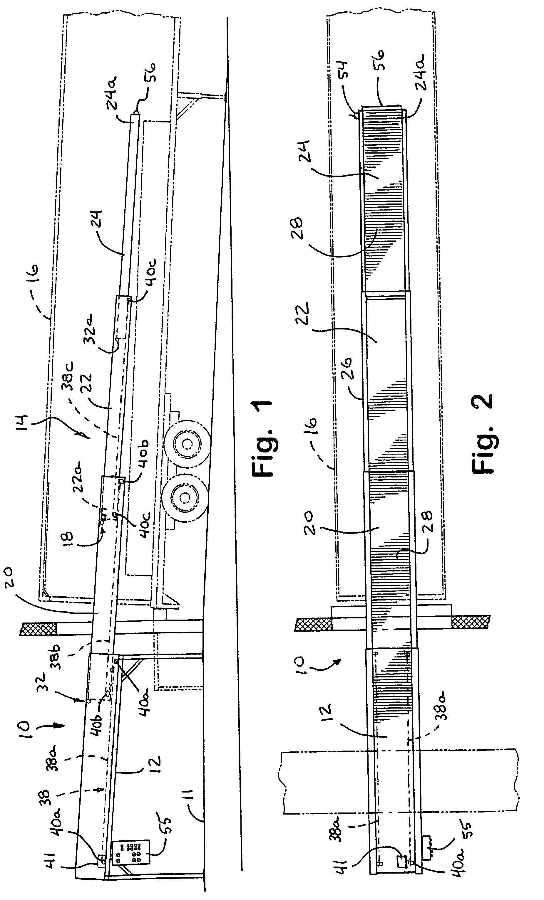
[0022]Referring now specifically to the drawings and the illustrative embodiments depicted therein, a cantilevered telescopic extendable conveyor or loader 10 includes a support structure or base structure 12 and one or more extendable conveyor units 14, which are extendable and retractable relative to one another and base structure 12 (FIGS. 1-5). Base or support structure 12 may be mounted at a floor or support surface 11 of a warehouse, loading dock or the like, where a truck trailer 16 may be positioned for loading packages and the like therein. The extendable units 14 are extendable outwardly from base structure 12 and into truck trailer 16 (as shown in FIGS. 1, 2 and 4) for loading the packages at the loading dock into the truck trailer 16. The extendable units 14 are cantileverly supported by the next inwardly or rearwardly positioned unit and the base structure and are nested within one another, such that the units may be fully retracted into base structure 12 to a stored po...


PUM


Abstract

An extendable conveyor includes a support structure, and at least one extendable unit that is supported in a cantilevered manner and that is movable between an extended position and a retracted position nested within the support structure. The extendable unit has at least one support roller for rollingly engaging at least one of another extendable unit and the support structure as the extendable unit is extended or retracted. The conveyor includes a braking device operable to limit rotation of at least one support roller via selective engagement of a braking element with the support roller. The braking device is activatable to disengage the braking element from the support roller in response to actuation of a user input. The braking element is biased to engage the braking element with the support roller when the braking device is deactivated.

Description

CROSS REFERENCE TO RELATED APPLICATION[0001]The present application claims benefit of U.S. provisional application, Ser. No. 60 / 698,409, filed Jul. 12, 2005, which is hereby incorporated herein by reference in its entirety.FIELD OF THE INVENTION[0002]The present invention relates generally to gravity loaders for loading packages and the like, such as into a truck / trailer, and more particularly, to a cantilevered telescopingly extendable gravity loader.BACKGROUND OF THE INVENTION[0003]Extendable loaders are often implemented at loading docks for trucks, trailers or the like. The gravity loaders are extendable into a truck / trailer and angled downward such that gravitational forces cause packages to move down the loaders along a plurality of rollers.[0004]The loaders may be extended to reach further into the trailer, in order to minimize the manual lifting and carrying of the packages, and retracted to a stored position to minimize the space taken up by the loader when not in use. Howe...

Claims


Application Information

Patent Timeline
Patent Type & Authority Patents(United States)
IPC IPC(8): B65G15/60
CPCB65G21/14B65G67/08
Inventor YANG, SHENGHONGMEDLEY, JAMES A
Owner KÖRBER SUPPLY CHAIN LLC
Learn More