
Wheelchair provided with legrest and calfrest

a technology for wheelchairs and calfs, which is applied in the field of wheelchairs provided with legrests, can solve the problems of uncomfortable sitting postures, inconvenient obstacles, and require substantial physical effort from users and/or their assistants

Inactive Publication Date: 2008-05-06
LIFE & MOBILITY DEV
View PDF15 Cites 31 Cited by
  • Summary
  • Abstract
  • Description
  • Claims
  • Application Information

AI Technical Summary

Benefits of technology

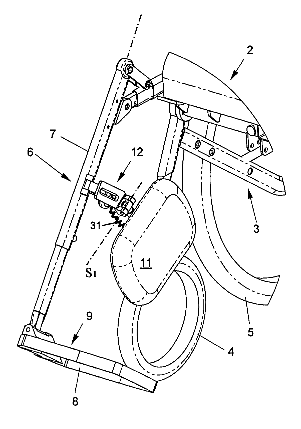
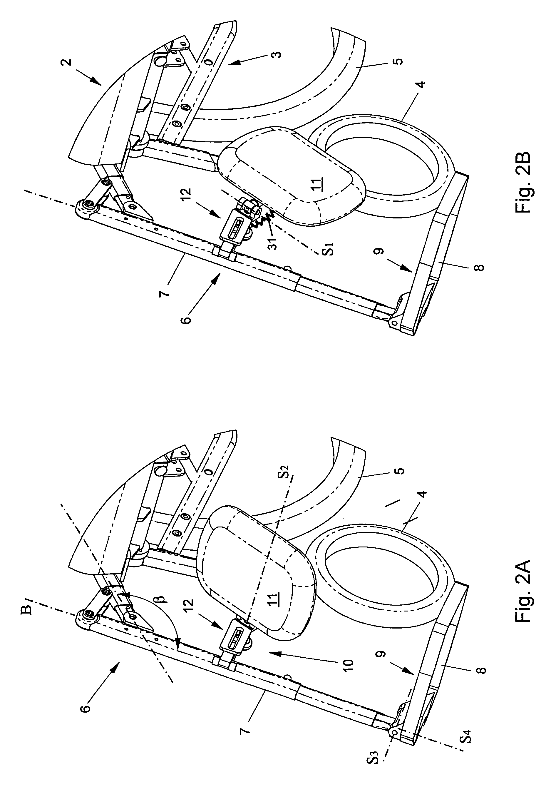
[0007]With a wheelchair according to the invention, the or each calfrest can be brought from a supporting to a non-supporting position, without traversing the space occupied by the legs of a wheelchair user when this user has placed his feet on the footrest. Consequently, the wheelchair can be readied for a transfer without the wheelchair user needing to take his legs from these footrests, while, accordingly, physical effort and an uncomfortable sitting posture are avoided. Moreover, the wheelchair user and / or his companion have their hands free for operating the calfrests or, optionally, other wheelchair parts. After the calfrests have been removed, the legs of the wheelchair user can be taken from the footrests and be placed on the road surface directly in front of the wheelchair, whereupon the footrests or the legrest in its entirety can be pivoted aside. Naturally, then, the path of travel is once again such that the space occupied by the legs placed on the road surface in front of the wheelchair is not traversed. After the section of road in front of the wheelchair has thus been cleared of obstacles, the wheelchair user can rise from the wheelchair unhindered, with or without the aid of a companion.
[0009]In an alternative advantageous embodiment according to the invention, each calfrest is pivotally connected to the legrest. As a result, the calfrest can be pivoted to a non-supporting position without, to that end, the rest needing to be detached. Hence, disassembly and assembly operations can be avoided and the risk of loss or theft (of separate parts) is limited. Naturally, a combination of the above-mentioned embodiments is possible too, wherein the calfrest is coupled with the legrest by means of a detachable pivot connection.
[0011]With such an arm construction, the calf plate can be fastened to a legrest of an existing wheelchair in a simple manner, while the arm construction, in particular the orientation of the pivot axis between the two arms, offers the freedom necessary for fastening the calfrest such that it can adequately support the legs of the wheelchair user in the supporting position, and its path of travel to the non-supporting position crosses no wheelchair parts.
[0013]In a particularly advantageous embodiment, mechanical drive means are provided with which the calfrest can be moved (semi)automatically between the supporting position, ready for use, and the non-supporting position, ready for transfer. For instance, biasing means can be provided which, when the calfrest is in the supporting position, bias the calfrest to the position ready for transfer. By activating the biasing means (for instance by lifting a blocking) the calfrest will then be urged by the bias force to the non-supporting position. With such drive means, readying the wheelchair for the purpose of transfer is simplified still further. Naturally, similar drive means can be provided for the or each footrest. Further, suitable blocking means can be provided for securing the calfrest in the supporting position against pivotal movement.

Problems solved by technology

Such a legrest contributes to a comfortable support of the legs of the user seated in the wheelchair, but upon a transfer of this user in and from the wheelchair it forms an inconvenient obstacle.
This leads to a very uncomfortable sitting posture that requires substantial physical effort from the user and / or his assistant.

Method used


Image

  • Wheelchair provided with legrest and calfrest
  • Wheelchair provided with legrest and calfrest
  • Wheelchair provided with legrest and calfrest

Examples


Embodiment Construction

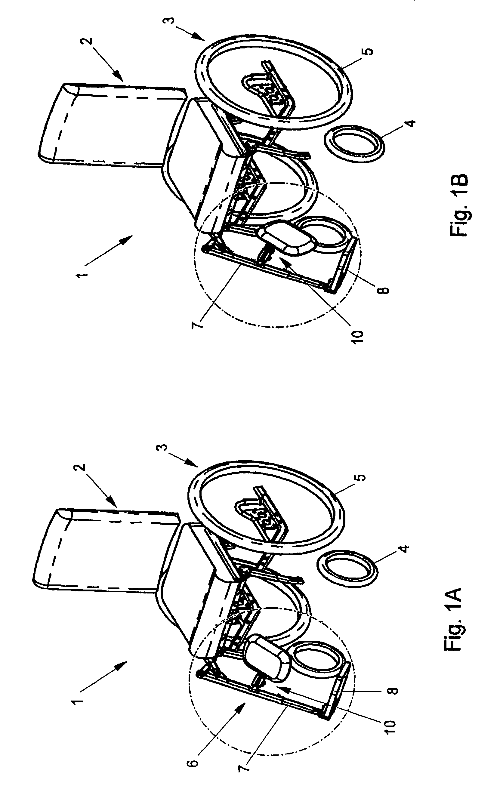
[0020]FIGS. 1A, B show a wheelchair 1 according to the invention, comprising a sitting support 2, borne by a wheeled substructure 3, provided with two pivotable front wheels 4 and two drivable rear wheels 5. Naturally, other substructure configurations are possible. The wheelchair 1 further comprises a legrest 6 which is substantially built up from a tubular frame part 7, a footrest 8 and calfrest 10 connected thereto which, in FIG. 1A, assumes a supporting position ready for use and in FIG. 1B, assumes a rearwardly pivoted position, ready for transfer.

[0021]The wheelchair 1 shown in FIG. 1A, B comprises one legrest 6, which is fastened to one side of the substructure 3 and which reaches from near a front edge of the sitting support 2, at a downwards inclination, adjacent the road surface. Alternatively, the wheelchair can comprise two legrests 6 (not specifically shown), attached to the two sides of the wheelchair 1, or one central legrest 6 extending in the central longitudinal pl...


PUM


Abstract

The invention relates to a legrest for a wheelchair, provided with a footrest and a calfrest. In a first, supporting position (ready for use), this footrest and calfrest are designed for supporting at least a part of a leg of a user seated during use in the wheelchair. The calfrest can be moved to a non-supporting, second position (ready for transfer), wherein the calfrest is located outside the space which is occupied by the legs of a wheelchair user upon sitting down in and / or rising from the wheelchair. The pivotal direction of the calfrest is then such that the path of travel between said first and second position is located substantially outside the space occupied by the legs of the wheelchair user in the first, supporting position.

Description

BACKGROUND OF THE DISCLOSURE[0001]1. Field of the invention[0002]The invention relates to a wheelchair provided with a legrest, in particular a legrest provided with a calfrest. Such wheelchairs are known.[0003]2. Description of the Prior Art[0004]With the known wheelchairs, the legrest usually comprises a frame part which is connected centrally to the wheelchair or on two sides, and which is provided with a footrest and calfrest, reaching from the frame part as far as in front of a seat of the wheelchair. Such a legrest contributes to a comfortable support of the legs of the user seated in the wheelchair, but upon a transfer of this user in and from the wheelchair it forms an inconvenient obstacle.[0005]It has already been proposed to design the or each legrest to be pivotable so that prior to a transfer, it can temporarily be pivoted sideways. The legs of the user seated in the wheelchair are then to be lifted from of the path of travel of the calfrest pivoting by. This leads to a...

Claims


Application Information

Patent Timeline
IPC IPC(8): B62M1/14A61G5/12
CPCA61G5/12A61G5/1075A61G2005/127A61G2005/128A61G5/127A61G5/128
Inventor JANSEN, MARTIN
Owner LIFE & MOBILITY DEV
Learn More