
Ground rod having induction discharge skin-effect plate

a technology of induction discharge and skin-effect plate, which is applied in the installation of lighting conductors, connection contact material, manufacturing tools, etc., to achieve the effect of reducing the electric potential increase of the ground, easy discharge, and increasing the critical surface area

Inactive Publication Date: 2008-04-29
KIM DONG JIN
View PDF3 Cites 7 Cited by
  • Summary
  • Abstract
  • Description
  • Claims
  • Application Information

AI Technical Summary

Benefits of technology

"The present invention provides a ground rod with an induction discharge skin-effect plate that overcomes the problems of conventional art. The ground rod has an induction discharge skin-effect plate that allows for easy discharge of electric current to the ground when a thunderbolt falls, while also reducing the electric potential increase of the ground. The ground rod also induces a large ground pole effect when a thunderbolt electric current is inputted by allowing moisture of surrounding soil to be inputted into a surrounding portion of the ground rod by inputting a moisture absorber into the interior of the ground rod. The ground rod has a connection part that allows for an electric potential discharge between the ground rod and the induction discharge skin-effect plate when a thunderbolt falls. The ground rod also has through grooves and a moisture absorber in the interior of the ground rod to facilitate the discharge of electric current and to reduce the risk of electrical arcing."

Problems solved by technology

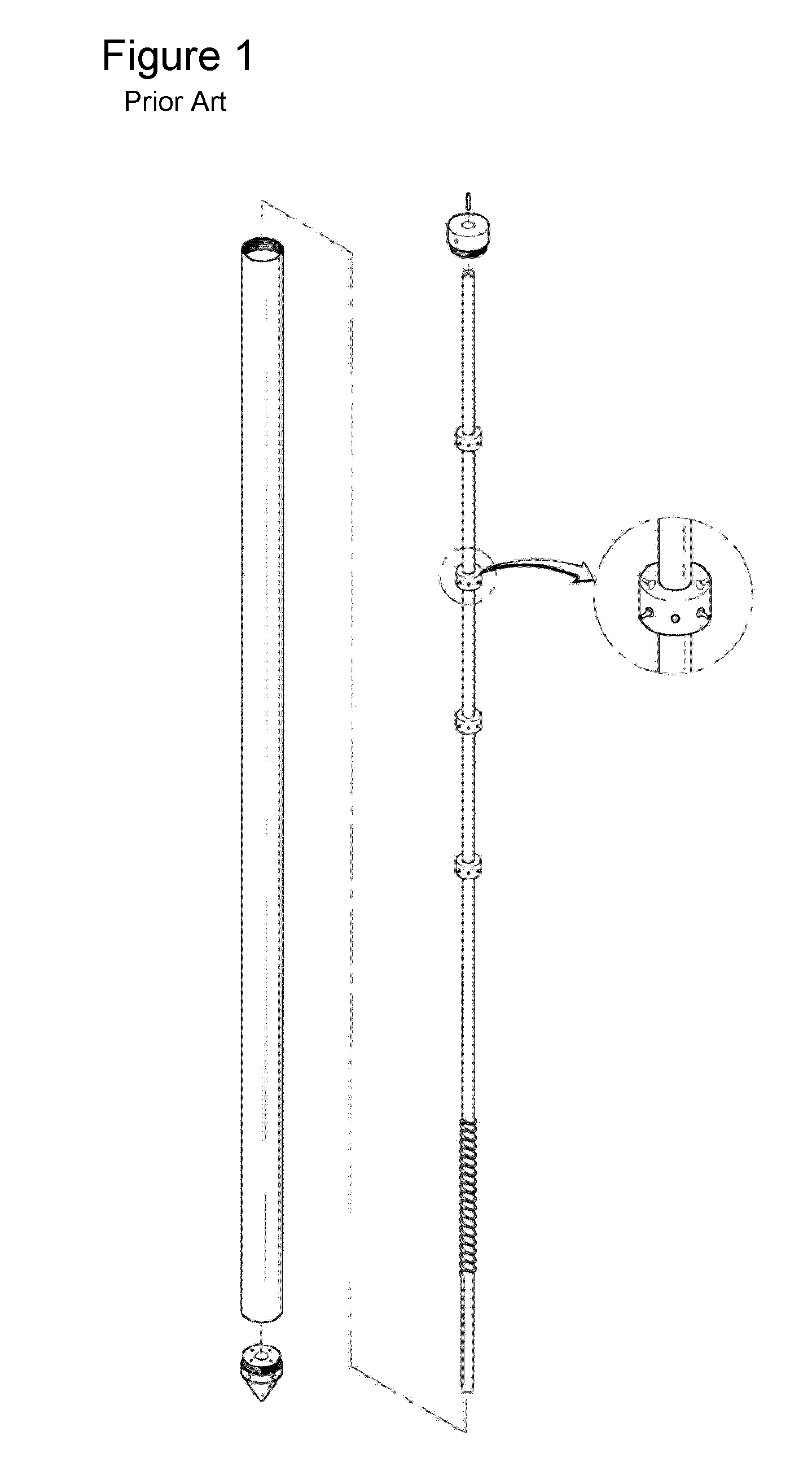
However, a ground impedance increases by an inherent resistance of the ground when a thunderbolt electric current is discharged to the ground through a ground rod, and a ground electric potential increases, so that an electric potential, which is applied to a protected instrument such as a large power facility instrument, a communication and weak electric current facility and an architectural facility, increases for thereby damaging the above facilities.
However, according to the needle ground rod of the Korean paten registration number 0339924, since a thunderbolt is applied through only the surface of the ground rod by a skin effect by a high frequency electric current when a thunderbolt falls, so that a resistance inductance causes many problems.

Method used


Image

  • Ground rod having induction discharge skin-effect plate
  • Ground rod having induction discharge skin-effect plate
  • Ground rod having induction discharge skin-effect plate

Examples


Embodiment Construction

[0024]The ground rod having an induction discharge skin-effect plate according to the present invention will be described with reference to the accompanying drawings.

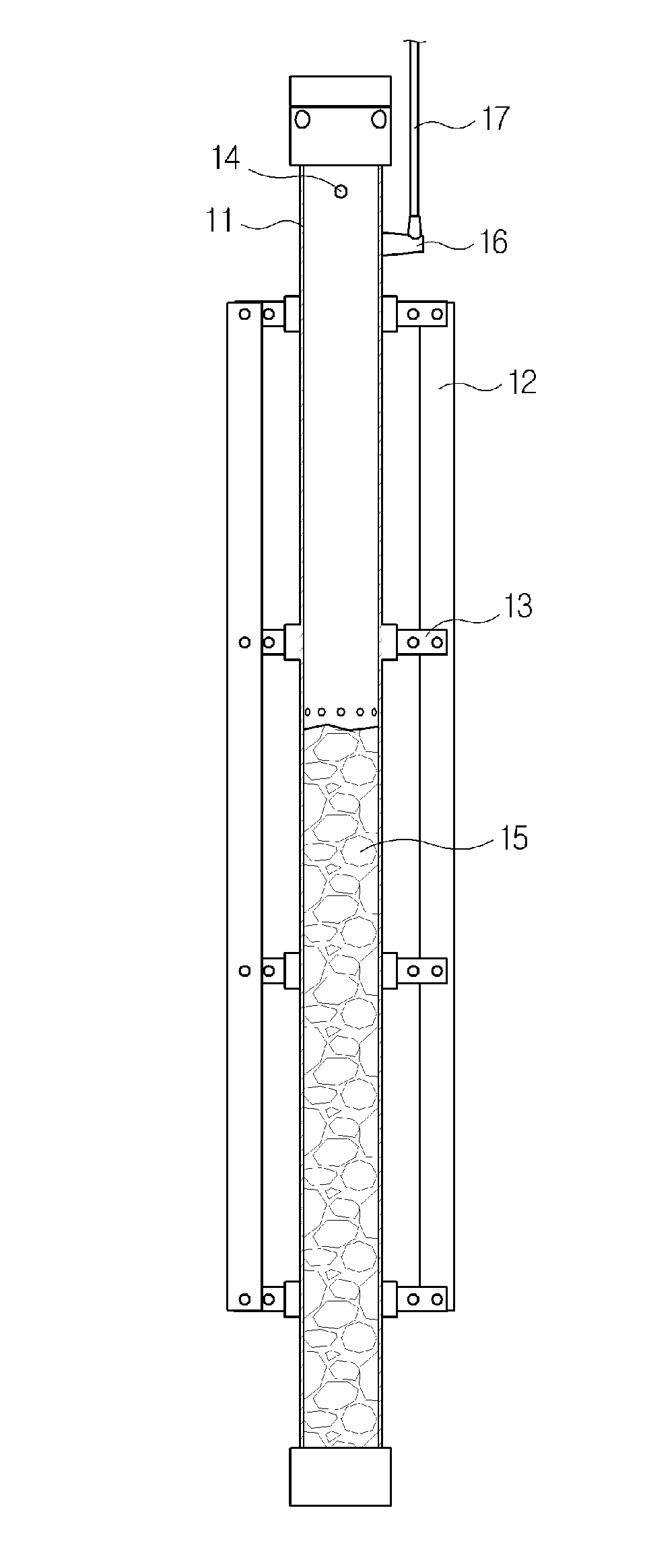
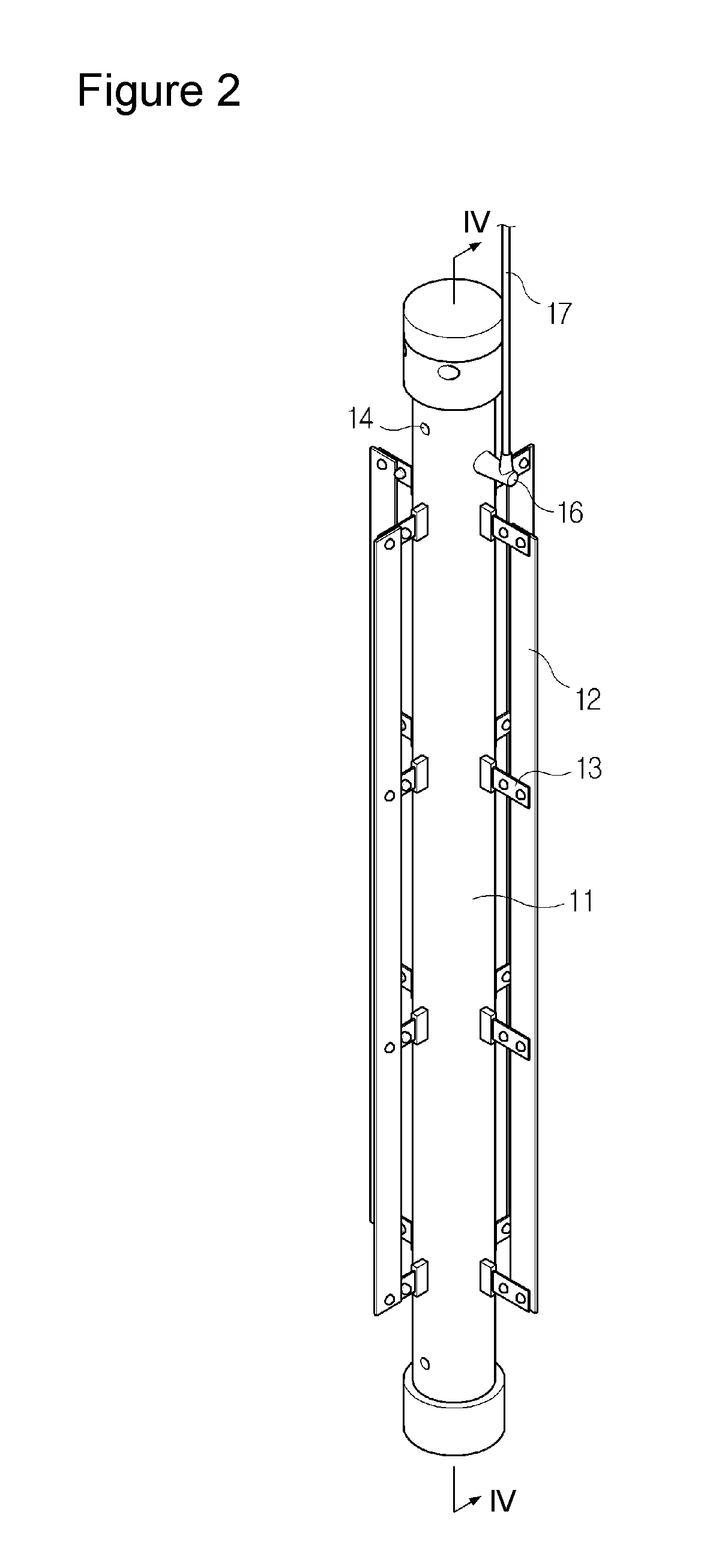
[0025]FIG. 2 is a perspective view illustrating a ground rod having an induction discharge skin-effect plate according to an embodiment of the present invention, FIG. 3 is a disassembled view of FIG. 1, FIG. 4 is a cross sectional view taken along the line IV-IV of FIG. 2, FIG. 5 is a view of a use state of a ground rod having an induction discharge skin-effect plate according to the present invention, and FIG. 6 is a view illustrating a ground rod having an induction discharge skin-effect plate according to another embodiment of the present invention.

[0026]As shown in FIGS. 2 and 3, a ground rod according to the present invention comprises a copper or conductive metallic ground rod 11, an induction discharge skin-effect plate 12 installed at a certain interval in a longitudinal direction of the ground rod 11, and a con...


PUM


Abstract

A ground rod having an induction discharge skin-effect plate is disclosed, in which an electric current inputted into a ground rod can be easily discharged to the ground by forming an induction discharge skin-effect plate in parallel with a ground rod at a certain interval and increasing a critical surface area when a thunderbolt falls. In addition, an electric potential increase of the ground can be lowered by allowing an electric potential discharge to take place between the upper and lower vertical portions of a ground rod and an induction discharge skin-effect plate when a thunderbolt falls.

Description

CROSS REFERENCE[0001]Applicant claims foreign priority under Paris Convention and 35 U.S.C. §119 to the Korean Patent Application No. 10-2006-0010675, filed Feb. 3, 2006 with the Korean Intellectual Property Office.BACKGROUND OF THE INVENTION[0002]1. Field of the Invention[0003]The present invention relates to a ground rod having an induction discharge skin-effect plate, and in particular to a ground rod having an induction discharge skin-effect plate in which an electric current inputted into a ground rod can be easily discharged to the ground by forming an induction discharge skin-effect plate in parallel with a ground rod at a certain interval and increasing a critical surface area when a thunderbolt falls. In addition, an electric potential increase of the ground can be lowered by allowing an electric potential discharge to take place between the upper and lower vertical portions of a ground rod and an induction discharge skin-effect plate when a thunderbolt falls.[0004]2. Descr...

Claims


Application Information

Patent Timeline
Patent Type & Authority Patents(United States)
IPC IPC(8): H02G13/00
CPCH01R4/66B30B9/02A23L3/00B09B3/40
Inventor KIM, DONG-JIN
Owner KIM DONG JIN
Learn More