Pivotal connector assembly

a connector and assembly technology, applied in the direction of threaded fasteners, screwdrivers, couplings, etc., can solve the problems of cumbersome and time-consuming, cumbersome coupling assemblies, and cumbersome coupling assemblies, etc., to improve the lateral support of the arm

Active Publication Date: 2008-04-29
CNH IND CANADA
View PDF13 Cites 7 Cited by
  • Summary
  • Abstract
  • Description
  • Claims
  • Application Information

AI Technical Summary

Benefits of technology

[0006]The present invention provides a connector assembly in pivotal support of an arm having an opening that extends therethrough. The connector assembly includes a first structural support plate in generally parallel alignment with, and spaced apart from, a second structural support plate. The first and second structural support plates are configured to receive the arm therebetween. The first support plate includes a first opening and the second support plate includes a second opening in general concentric alignment with the first opening in the first support plate. The connector assembly further includes a collar attached at, and having a bore or passage in concentric relation to, the opening in the first structural support plate. The collar includes a collar pin passage aligned generally perpendicular to the passage. The connector assembly further includes a connector pin pivotally coupling the arm between the first and second structural support plates. The connector pin is received through the bore of the collar, the first structural support plate opening, the second structural support plate opening and the opening in the arm in pivotal support of the arm. The connector pin includes a first end and a second end, the first end having an exterior threaded portion and the second end having a connector pin opening extending diametrically therethrough. The connector further includes a connector pin nut having threaded interior configured to receive the exterior threaded portion of the connector pin. The connector assembly further includes a lock pin received through the connector pin opening of the connector pin and the collar pin opening of the collar. The lock pin secures a location or position of the connector pin relative to the first and second structural support plates. Rotation of the connector pin nut, in combination with the lock pin fixed in the connector pin and collar, causes the tightens or squeezes the first support plate and the second plate against the support arm therebetween, which enhances lateral support of the arm.
[0009]The connector assembly generally includes a first structural support plate in generally parallel alignment with, and spaced apart from, a second structural support plate. The first and second structural support plates are configured to receive the second end of the arm therebetween, as well as a vertical shaft or support of the caster assembly. The first support plate includes a first opening and the second support plate includes a second opening in general alignment with the first opening in the first support plate. The connector assembly further includes a collar attached at, and having a bore or passage in concentric relation to, the first opening in the first support plate. The collar further includes a collar pin opening aligned generally perpendicular to the passage. The connector assembly further includes a connector pin pivotally coupling the arm between the first and second structural support plates. The connector pin is received through the bore in the collar, the first structural support plate opening, the second structural support plate opening and the opening through the second end of the arm. The connector pin includes a first end having an exterior threaded portion and a second end having a connector pin opening extending therethrough. The connector assembly further includes a connector pin nut having threaded interior to receive the exterior threaded portion of the connector pin. The connector assembly further includes a lock pin received through the connector pin opening. Rotating the connector pin nut relative to the connector pin tightens or squeezes the first and second structural support plates against the support arm therebetween. The connector assembly thereby allows the support arm to pivot about the connector pin between the first and second structural support plates, as well as enhances lateral support of the arm to resist forces acting on the arm associated with operation of the implement on an agricultural terrain or field.
[0010]In another embodiment, the present invention provides a method of pivotally coupling a first end of a support arm between a first support and a second support of a housing. The method includes the steps of receiving the first end of the support arm between the first and second support of the housing; inserting a connector pin through a first opening in the first support, a second opening in the second support, an opening in the first end of the support arm, and a collar that defines a passage in concentric relation to the first opening in the first support; securing the position of the connector pin relative to the housing by inserting a lock pin through a connector pin opening of the connector pin and a collar opening of the collar; and squeezing the first and second supports against the first end of the support arm therebetween.

Problems solved by technology

However, this certain known coupling assembly 20 has drawbacks.
Cutting the threaded portions at both ends 60, 62, of the coupling pins 46, 48 is cumbersome and time consuming.
Moreover, cutting the polygonal-shaped end portions of the bores 80, 82 in the collars 76, 78 to accommodate and restrain the coupling nuts 70, 72 is also costly and time consuming.

Method used


Image

  • Pivotal connector assembly
  • Pivotal connector assembly
  • Pivotal connector assembly

Examples


Embodiment Construction

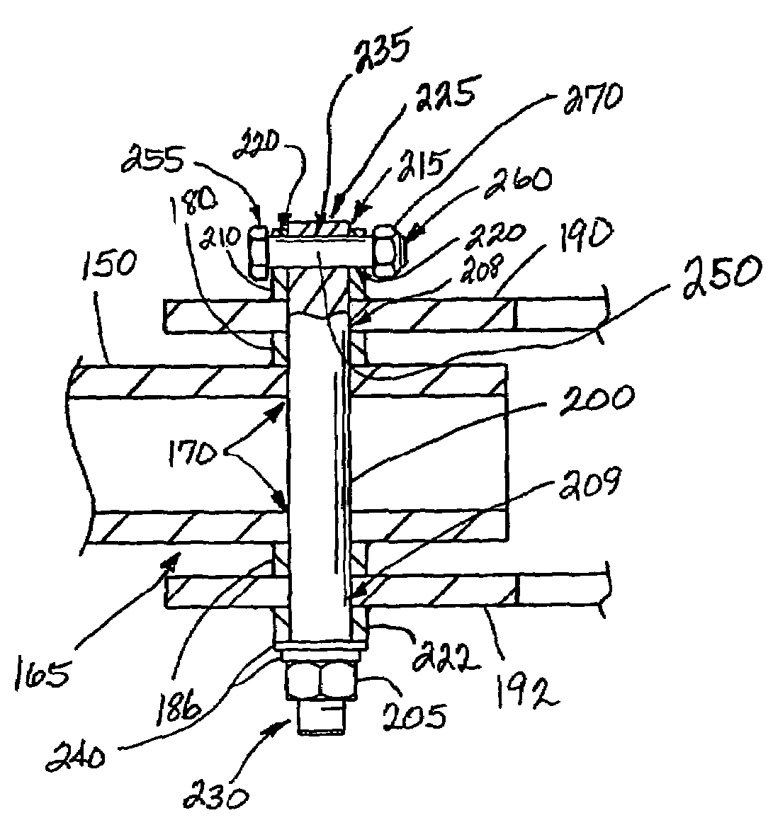
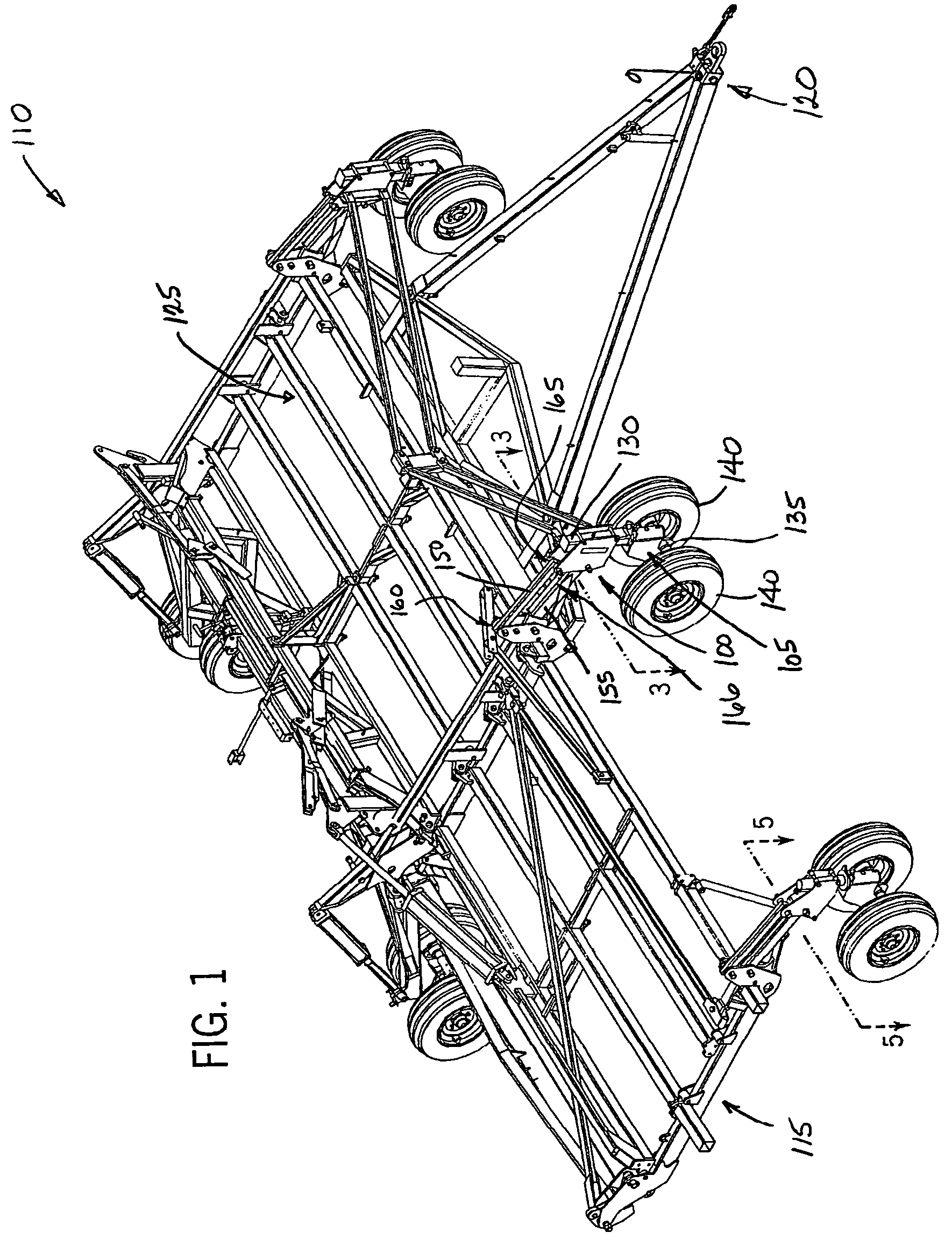
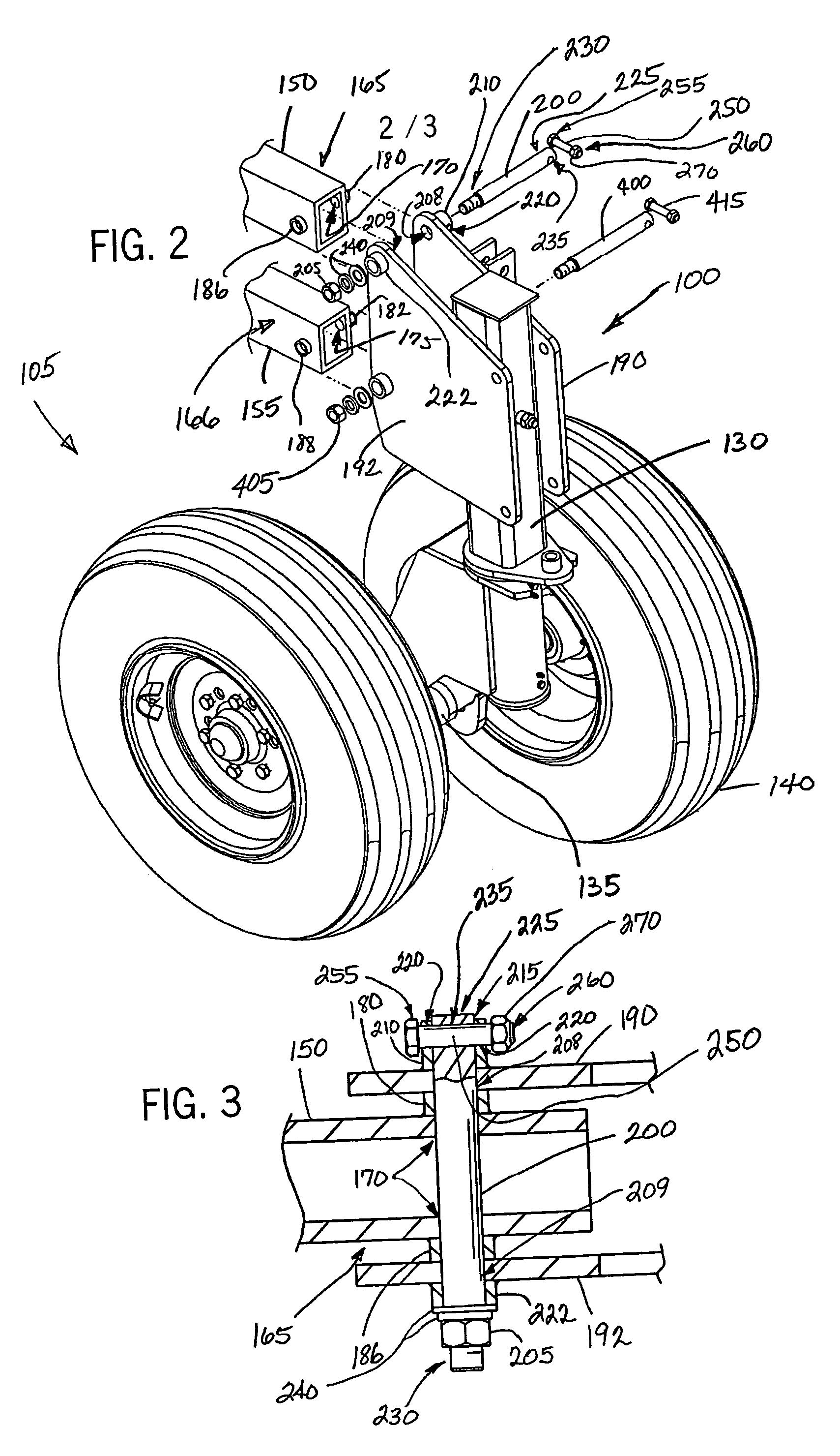
[0019]A wide variety of machines or systems could be constructed in accordance with the invention defined by the claims. Hence, even though the exemplary embodiment of a connector assembly 100 in accordance with the invention will be generally described with reference to a caster assembly 105 of an agricultural implement 110 as shown in FIG. 1, the application of the connector assembly 100 is not so limited. The connector assembly 100 of the invention could be employed to couple, mount, or support by a wide variety of structures, machines, tools or mechanical assemblies, etc., and is not limiting on the invention.

[0020]As shown in FIG. 1, the preferred agricultural implement 110 includes a mainframe 115 interconnected with a hitch 120 and a tool bar 125. The hitch 120 is configured to be coupled to a tow vehicle (not shown). The tool bar 125 is configured to support various tools (not shown) to be used in agricultural planting, tilling, etc. operations. The types of tools can vary. ...


PUM


Abstract

A connector assembly pivotally couples a caster assembly with a pivot arm of an agricultural implement. The connector assembly includes first and second structural support plates having openings to receive a connector pin therethrough pivotally coupling the arm between the plates. A fixed collar having a bore, and a lock pin passage aligned perpendicular thereto, is fixed at one of the first or second structural support plates to receive the connector pin therethrough. The connector pin includes a first end having an exterior threaded portion and a second end having a connector pin opening. The connector pin opening and the lock pin opening receive a lock pin therethrough that secures a position of the connector pin in the collar. Tightening a nut at the threaded end of the connector causes the structural support plates to squeeze against the arm, enhancing lateral support of the arm.

Description

FIELD OF INVENTION[0001]The invention relates to a connector assembly and, more particularly, to a connector assembly having a lock pin configured to pivotally couple a pivot arm with a caster assembly of an agricultural implement.BACKGROUND OF INVENTION[0002]Agricultural implements typically employ numerous types of pivotal connector assemblies in coupling various tools, structures, caster or wheel assemblies, etc. associated with operation of the agricultural implement.[0003]A certain known connector assembly 20 is illustrated on FIGS. 4 and 5. The connector assembly 20 is generally employed to pivotally couple a vertical shaft 25 of a rotatable caster or caster assembly 30 to pivot arms or linkages 36, 38 of an agricultural implement (not shown). The connector assembly 20 generally includes a housing or bracket 40 that in combination with one or more pins 46, 48 pivotally connects the pivot arms or linkages 36, 38 with the caster assembly 30. The preferred housing 40 includes a f...

Claims


Application Information

Patent Timeline
Patent Type & Authority Patents(United States)
IPC IPC(8): F16J1/18
CPCA01B51/04Y10T403/32868Y10T403/587Y10T403/32893Y10T403/7123F16B2200/71
Inventor SEIB, DAVID D.
Owner CNH IND CANADA
Why Eureka
Try Eureka