
Optical receptacle and optical module with optical receptacle

a technology which is applied in the field of optical receptacle and can solve the problems of disadvantageous increase in size of optical module with optical receptacle, and achieve the effects of small connection loss, easy attachment or removal, and easy adjustment of optical fiber position

Inactive Publication Date: 2008-04-29
NTT ELECTORNICS CORP
View PDF5 Cites 7 Cited by
  • Summary
  • Abstract
  • Description
  • Claims
  • Application Information

AI Technical Summary

Benefits of technology

The present invention provides an optical receptacle and an optical module with the receptacle that can be reduced in size. The optical receptacle has a space between the side surface of the stub ferrule and the inner surface of the housing, which reduces the connection loss and allows for easy adjustment of the optical axis. The optical module with the receptacle is smaller and more portable. The invention also provides an optical receptacle that can be easily attached and detached from the optical module and an optical module with the receptacle that can easily adjust the optical axis.

Problems solved by technology

Therefore, the optical module with optical receptacle 90 disadvantageously increases in size.

Method used


Image

  • Optical receptacle and optical module with optical receptacle
  • Optical receptacle and optical module with optical receptacle
  • Optical receptacle and optical module with optical receptacle

Examples


first embodiment

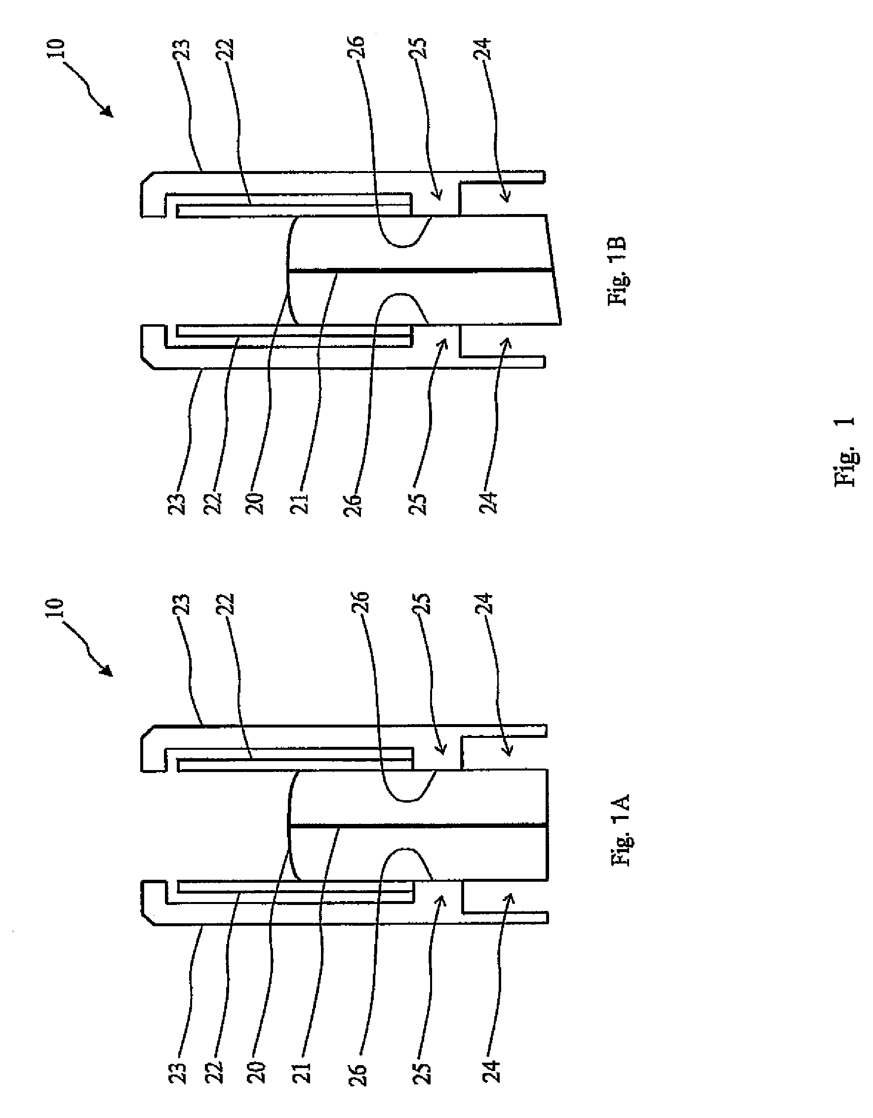
[0028]A first embodiment of the present application is an optical receptacle including a columnar stub ferrule having an optical fiber inserted into a center line connecting both opposite end faces; a cylindrical sleeve into which a part of the stub ferrule is inserted; and a housing in which a through hole is formed, which houses the stub ferrule and the sleeve in the through hole, which holds a part on a side on which the stub ferrule is not inserted into the sleeve, with a projecting portion formed in the through hole, and which surrounds a side surface of the stub ferrule on the side on which the stub ferrule is not inserted into the sleeve. The optical receptacle has a space between the side surface of the stub ferrule on the side on which the stub ferrule is not inserted into the sleeve and an inner peripheral surface of the housing opposing the side surface.

[0029]An optical receptacle 10 according to the first embodiment will be described below with reference to FIG. 1. FIG. ...

second embodiment

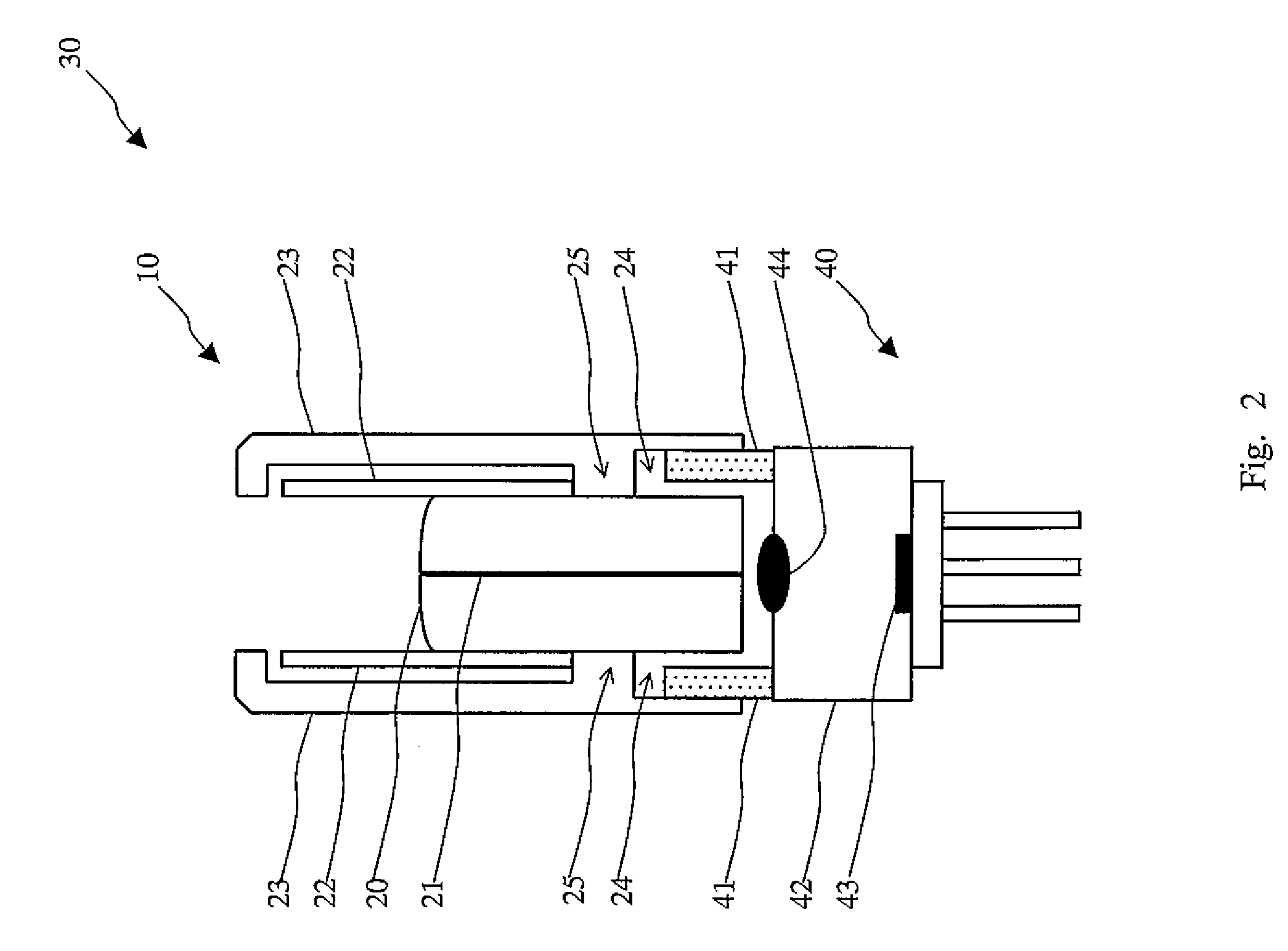
[0043]A second embodiment of the present application is an optical module with optical receptacle including: an optical receptacle having a columnar stub ferrule having an optical fiber inserted into a center line connecting both opposite end faces, a cylindrical sleeve into which a part of the stub ferrule is inserted, and a housing in which a through hole is formed, which houses the stub ferrule and the sleeve in the through hole, which holds a part on a side on which the stub ferrule is not inserted into the sleeve, with a projecting portion formed in the through hole, and which surrounds a side surface of the stub ferrule on the side on which the stub ferrule is not inserted into the sleeve and having a space between the side surface of the stub ferrule on the side on which the stub ferrule is not inserted into the sleeve and an inner peripheral surface of the housing opposing the side surface; a cylindrical optical receptacle holding sleeve matched to the space of the housing a...


PUM


Abstract

An optical receptacle according to the invention includes a columnar stub ferrule having an optical fiber inserted into a center line connecting both opposite end faces; a cylindrical sleeve into which a part of the stub ferrule is inserted; and a housing in which a through hole is formed, which houses the stub ferrule and the sleeve in the through hole, which holds a part on a side on which the stub ferrule is not inserted into the sleeve, with a projecting portion formed in the through hole, and which surrounds a side surface of the stub ferrule on the side on which the stub ferrule is not inserted into the sleeve. The optical receptacle has a space between the side surface of the stub ferrule on the side on which the stub ferrule is not inserted into the sleeve and an inner peripheral surface of the housing opposing the side surface.

Description

[0001]The present application is based on, and claims priority from, J.P. Application 2005-255516, filed Sep. 2, 2005, the disclosure of which is hereby incorporated by reference herein in its entirety.BACKGROUND OF THE INVENTION[0002]1. Field of the Invention[0003]The present invention relates an optical receptacle in which an optical connector is connected to an optical semiconductor device such as a light emitting diode or a photodiode and a module with the optical receptacle.[0004]2. Description of the Related Art[0005]Since a conventional optical module using an optical receptacle is good in versatility and is easy to handle, the degree of importance of the optical module gradually increases, and the optical module is requested to be further reduced in size.[0006]A conventional optical module with optical receptacle will be described below by using an optical module with optical receptacle 90 disclosed in Japanese Patent Application Laid-open No. 2004-93696 as an example with r...

Claims


Application Information

Patent Timeline
Patent Type & Authority Patents(United States)
IPC IPC(8): G02B6/36
CPCG02B6/421G02B6/4292
Inventor NISHIZAWA, TOSHIKIKOBAYASHI, KENJI
Owner NTT ELECTORNICS CORP
Learn More