Liquid supplying method

a liquid supply and liquid technology, applied in the direction of printing, other printing apparatus, etc., can solve the problems of limited driving force that can be generated by the negative pressure generating mechanism, difficult to reduce the overall size of the printer, and loud noise and larger vibration

Inactive Publication Date: 2008-04-29
CANON KK
View PDF4 Cites 0 Cited by
  • Summary
  • Abstract
  • Description
  • Claims
  • Application Information

AI Technical Summary

Benefits of technology

[0008]The present invention is directed to a liquid-supplying method of a pit-stop supplying type in which a negative-pressure generating member is applied so that a liquid-supply operation can be smoothly and properly performed.
[0012]In one embodiment, the method includes setting the amount of negative pressure generated by the negative-pressure generating member when the liquid is supplied to each first liquid-tank component from the corresponding second liquid-tank component within a range such that liquid in discharge nozzles provided in the liquid discharge unit is prevented from flowing in a direction opposite to a discharging direction of the liquid discharge unit. Accordingly, this can achieve a state where the liquid is always ready to be discharged.
[0016]Since the magnitude of negative pressure generated in each first liquid-tank component is controlled such that the magnitude of the negative pressure generated during a liquid-supply operation is greater than that in a state other than the liquid-supply operation, the difference in pressure between each first liquid-tank component and the corresponding second liquid-tank component can be made large when the liquid-supply operation is to be performed. Accordingly, the time required for the liquid-supply operation can be shortened.
[0017]Furthermore, since the magnitude of the negative pressure generated by the negative-pressure generating member with respect to each first liquid-tank component may be controlled based on a determined amount of liquid to be supplied to the first liquid-tank component, the liquid-supply operation can be performed according to the amount of liquid consumption in the first liquid-tank component. Moreover, since the liquid may be supplied to the first liquid tank from the second liquid tank when the detected orientation is within a predetermined range, the liquid-supply operation can be performed in a state where the difference in pressure between each first liquid-tank component and the corresponding second liquid-tank component is at a suitable value. Accordingly, this can prevent problems such as leaking of the liquid through the discharge nozzles and an inability to supply the liquid to each first liquid-tank component. Furthermore, as described above, the negative pressure generated by the negative-pressure generating member when the liquid-supply operation is performed may be set within a range such that the liquid in the discharge nozzles provided in the liquid discharge unit is prevented from flowing in a direction opposite to the discharging direction of the liquid discharge unit, thereby achieving a state where the liquid is always ready to be discharged. Accordingly, a recovery process for the discharge nozzles is not necessary, and a waste of liquid is thus prevented. Moreover, as described above, when the liquid is to be supplied to each of the first liquid-tank components, the magnitude of the negative pressure generated by the negative-pressure generating member does not necessarily need to be increased for every first liquid-tank component. Accordingly, the liquid-supply operation can be performed according to the amount of liquid consumption in each first liquid-tank component. Furthermore, since electricity may be applied to the negative-pressure generating member with respect to each first liquid-tank component when the liquid-supply operation is to be performed, and the negative-pressure generating member may be formed of a shape-memory material, the elastic coefficient of the negative-pressure generating member can be increased, whereby the negative pressure can accordingly be increased. Moreover, since the amount of electricity applied to the negative-pressure generating member with respect to each first liquid-tank component may be controlled depending on the amount of liquid to be supplied to the first liquid-tank component, the magnitude of the negative pressure with respect to each first liquid-tank component can be controlled based on the amount of liquid consumption in the first liquid-tank component. Accordingly, the liquid-supply operation can be performed according to the amount of liquid consumption in each first liquid-tank component, thus contributing to lower power consumption.

Problems solved by technology

This is problematic in view of louder noise and larger vibration during the printing operation.
According to Japanese Patent Laid-Open No. 8-323996, however, the sub tank and the main tank must be positioned vertically with respect to each other, and therefore, an overall size reduction of a printer is difficult.
Moreover, a driving source for an ink-supply operation is defined by a negative-pressure generating mechanism provided inside the sub tank, and a driving force that can be generated by the negative-pressure generating mechanism is limited to an extent that discharge nozzles can be maintained in a proper condition.
As a result, the ink-supply operation takes a large amount of time.
If such method type is applied to the structure disclosed in Japanese Patent Laid-Open No. 8-323996, the printing operation has to pause for a long period of time if the ink-supply operation takes a large amount of time.
Furthermore, if the printer is tilted at an angle, there may be cases where, for example, the ink cannot be supplied to the sub tank depending on the angle, or the ink may leak through the nozzles due to oversupplying of ink.

Method used


Image

  • Liquid supplying method
  • Liquid supplying method
  • Liquid supplying method

Examples


first embodiment

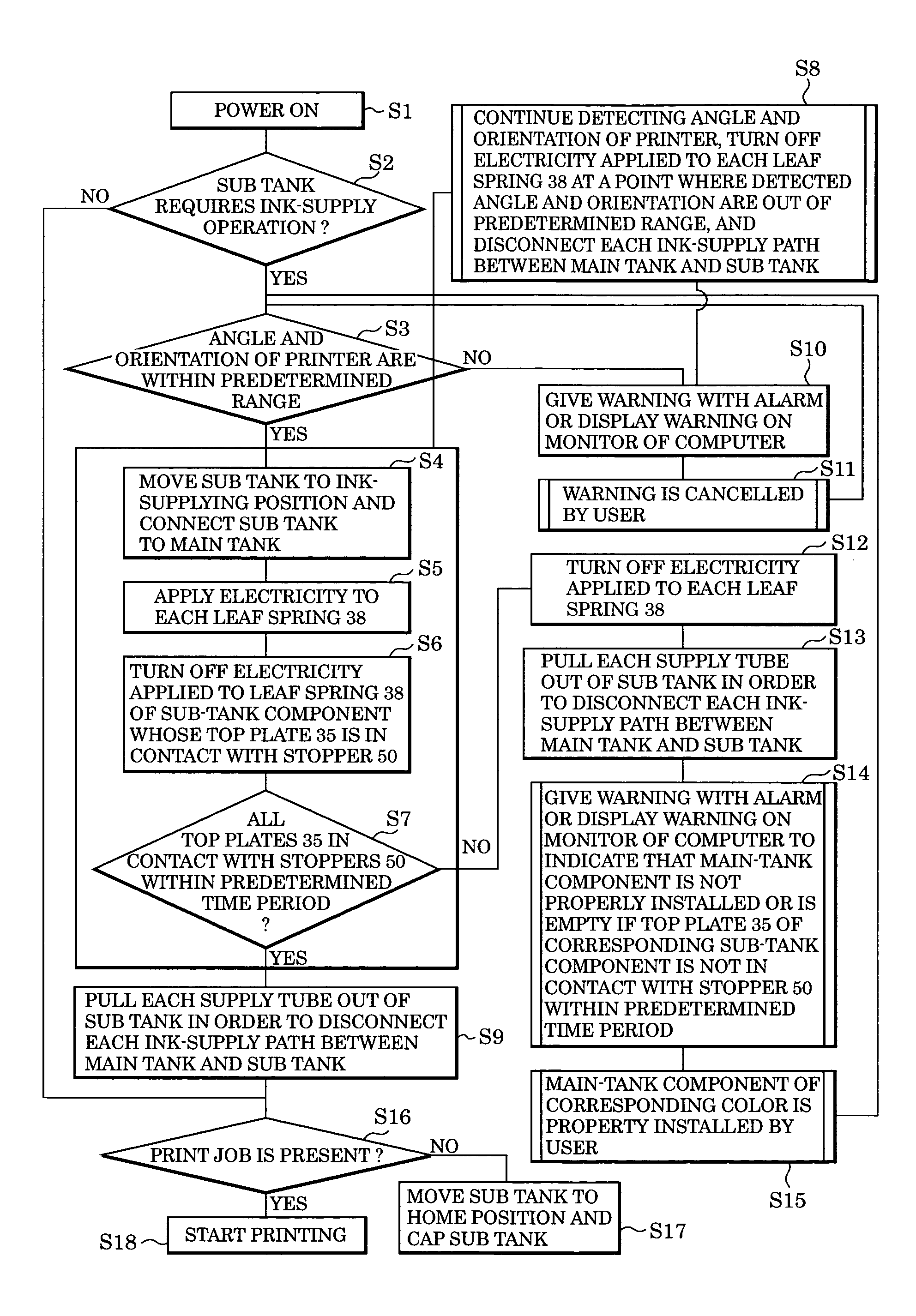
[0037]An image formation device according to a first embodiment of the present invention is directed to a printer of a pit-stop ink-supplying type in which an ink-supply path extending between a main tank and a sub tank is connected only when an ink-supply operation is performed.

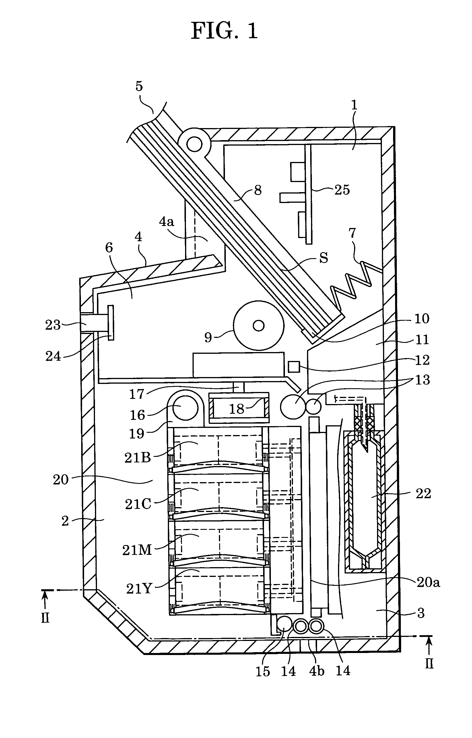
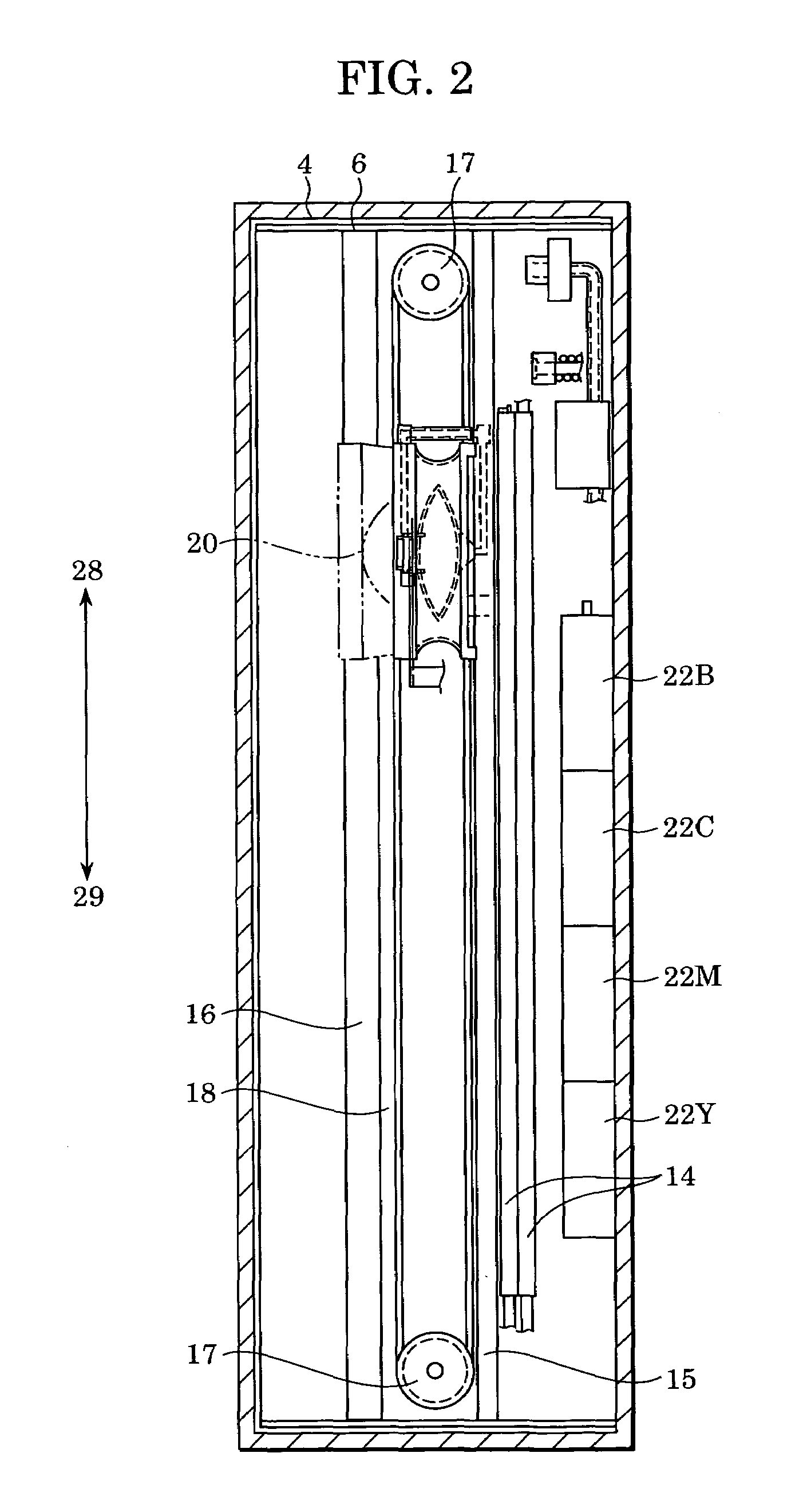
[0038]FIGS. 1 and 2 are cross-sectional views of an inkjet printer defining an image formation device according to the first embodiment of the present invention. An image formation device according to the first embodiment is a serial-scanning type in which a liquid discharge head is movable in a main scanning direction. Referring to FIG. 1, a printer body mainly includes, for example, a medium-feeding element 1 for feeding printing media S; a printing element 2 that performs a printing operation; and an ink-refilling element 3 that performs an ink-refilling operation.

[0039]Reference numeral 4 indicates a cover disposed on the exterior of the printer body, and reference numeral 5 indicates a tray on which mul...

second embodiment

[0083]In the first embodiment, each leaf spring 38 is formed of a bent shape-memory plate material and is disposed inside the corresponding sub-tank component of the sub tank 20. In the second embodiment, coil springs are used in place of the leaf springs 38, such that these coil springs are disposed on the exterior of the corresponding sub-tank components of the sub tank 20. This is advantageous especially in a case where the ink and the shape-memory material have a problem in view of compatibility.

[0084]FIGS. 10 to 13 are perspective views in which electrical-wire sections are not shown. FIGS. 10 and 12 illustrate a state where one of the sub-tank components of the sub tank 20 is filled with ink, whereas FIGS. 11 and 13 illustrate a state where a certain amount of ink in the sub-tank component is consumed. FIGS. 10 and 11 illustrate an example in which a pair of compression coil springs 80 is disposed between opposite-side protrusions of the top plate 35 and opposite-side protrusi...

third embodiment

[0085]Although the first and second embodiments describe a printer of a pit-stop ink-supplying type, a printer according to a third embodiment of the present invention is directed to a tube-equipped ink-supplying type in which the sub tank 20 and the main tank 22 are constantly connected to each other via a tube.

[0086]Referring to FIG. 15, a carriage 1001 supports an inkjet print head 1002 and a sub tank 1010 disposed thereon. The sub tank 1010 is connected to a main tank 1003 via a tube 1004 such that ink contained in the main tank 1003 can be supplied to the sub tank 1010 via the tube 1004. Reference numeral 1007 indicates printing paper, and reference numeral 1008 indicates a capping member that seals discharge nozzles of the inkjet print head 1002 when the printer is in a power-off state or in a stand-by state so as to prevent the ink in the discharge nozzles from drying out. A section that connects the tube 1004 to the sub tank 1010 is provided with a valve, which is not shown....


PUM


Abstract

A liquid-supplying method includes the steps of controlling a magnitude of negative pressure generated by a negative-pressure generating member provided in each of first liquid-tank components included in a first liquid tank such that the magnitude of the negative pressure generated during a liquid-supply operation is greater than that in a state other than the liquid-supply operation, detecting an amount of liquid consumption in each first liquid-tank component, determining an amount of liquid to be supplied to each first liquid-tank component based on the detection result, and controlling the magnitude of the negative pressure generated by the negative-pressure generating member with respect to each first liquid-tank component based on the determined amount of liquid to be supplied to the first liquid-tank component.

Description

BACKGROUND OF THE INVENTION[0001]1. Field of the Invention[0002]The present invention relates to a liquid supplying method for supplying ink used for image formation on a recording medium or for supplying processing liquid used for adjusting the printing quality of ink to be discharged onto a printing medium.[0003]2. Description of the Related Art[0004]An example of a typical inkjet printer that forms an image by discharging ink is a serial-scanning type. An inkjet printer of this type is provided with a cartridge that includes an ink-discharging print head and an ink tank that are detachably combined with each other. Such a cartridge is disposed on a carriage. By driving the carriage in a main scanning direction and feeding printing paper in a sub scanning direction, the inkjet printer performs a printing operation in a serial-scanning manner.[0005]In an inkjet printer of a serial-scanning type, every time the ink in the ink tank becomes empty, the ink tank must be replaced with a ...

Claims


Application Information

Patent Timeline
Patent Type & Authority Patents(United States)
IPC IPC(8): B41J2/195B41J2/175B41J29/02
CPCB41J2/17509B41J2/17513B41J2/17556B41J2/17566B41J2/17596B41J29/02
Inventor OKAMOTO, HIDEAKI
Owner CANON KK
Why Eureka
Try Eureka