
Method of controlling vibration damping in a helicopter, and apparatus implementing the method

a technology of vibration damping and helicopter, which is applied in the direction of propellers, propulsive elements, water-acting propulsive elements, etc., can solve the problems of affecting the stability of the helicopter and the flight comfort, affecting the flight comfort, so as to avoid premature wear of mechanical parts and dampers, the effect of controlling vibration

Inactive Publication Date: 2008-04-22
EUROCOPTER
View PDF9 Cites 6 Cited by
  • Summary
  • Abstract
  • Description
  • Claims
  • Application Information

AI Technical Summary

Benefits of technology

[0010]The present invention seeks to remedy the drawbacks of known dampers, and to control the vibration generated by the drag movements of the blades in all operating configurations of the helicopter. The present invention thus serves to control instability phenomena, in particular ground resonance and air resonance, while avoiding premature wear of mechanical parts and of the dampers.
[0028]This apparatus presents the advantage of being controlled and consequently easily adjustable to different applications. The dampers can thus be controlled so as to damp low frequency vibrations (lower than the frequency of rotation of the rotor) only when necessary. There is thus no unnecessary dissipation of energy.
[0031]Such a damper presents the advantage of operating at temperatures lying in the range −40° C. to +150° C. Magneto-rheological fluids present very little variation in stiffness over this temperature range. In addition, the impurities that appear during manufacture and use of the damper do not spoil its operation. Magneto-rheological dampers can also be controlled by electric current of the order of 1 amp (A) to 2 A at low voltage (12 volts (V) to 24 V). Their characteristics vary with temperature, but this variation can be compensated by adjusting the magnetic field. The response time of such dampers is also short. The changeover time to go from 10% to 90% of the force generated by the damper for a given excitation is 8 milliseconds (ms).
[0032]Another advantage is associated with the great simplicity with which such dampers can be controlled.

Problems solved by technology

Drag movements give rise to vibration in the form of oscillations, degrading the stability of the helicopter and comfort in flight.
Drag movement also induces longitudinal and lateral forces in the fuselage that generate pitch and roll movements, and also parasitic movements in the drive system.
If the frequencies of the fuselage and rotor modes are close enough together and if these modes are insufficiently damped, then the drag movements of the blades and the movements of the structure will amplify each other mutually and run the risk of becoming dangerous.
If a drag damper presents a high degree of damping, then the hub which connects the blades to the rotary drive shaft of the rotor will be subjected to very large forces throughout the time of flight, leading to high levels of fatigue and to a risk of mechanical parts rupturing.
Such dampers often present reliability problems, and they are also very expensive.

Method used


Image

  • Method of controlling vibration damping in a helicopter, and apparatus implementing the method
  • Method of controlling vibration damping in a helicopter, and apparatus implementing the method
  • Method of controlling vibration damping in a helicopter, and apparatus implementing the method

Examples


Embodiment Construction

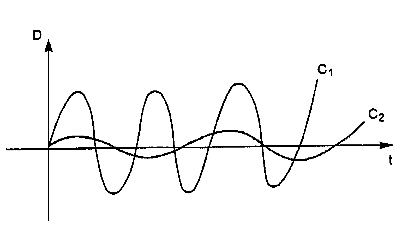
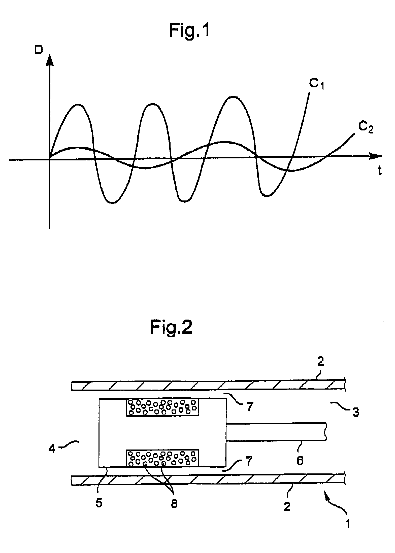
[0039]The drag movements of the blades generate oscillations of two types. The first type of oscillation presents the same frequency as that of the helicopter rotor, and it is referred to as the forced frequency. The second type of oscillation corresponds to drag oscillations presenting a natural frequency and an amplitude that are smaller than the frequency and the amplitude of the oscillations of the first type. These two types of oscillation are referred to respectively as the forced response and the natural response of the blades. These responses are shown diagrammatically in FIG. 1 by means of curves C1 and C2.

[0040]The control apparatus of the invention comprises a drag damper 1 associated with each blade. The damper is preferably a magneto-rheological damper 1, shown diagrammatically and in part in FIG. 2. The damper 1 comprises a frame 2 defining a first chamber 3 and a second chamber 4. The magneto-rheological fluid is moved from one chamber to the other and back again by m...


PUM


Abstract

The present invention relates to a method of controlling a drag damper for a helicopter blade under all operating configurations of the helicopter, the method consisting in:a) measuring the elongation of the damper;b) amplifying the measured signal and filtering out noise;c) isolating the natural response of the blade corresponding to the drag movement of the blade from the forced response imposed by a rotor driving the blades; andd) analyzing in real time the natural response and adjusting the damping as a function of the analysis.

Description

[0001]The present invention relates to a technical field of helicopters, and more particularly to the field of optimizing the conditions of use said helicopters.BACKGROUND OF THE INVENTION[0002]Helicopters have rotors driving blades. Rotation of the blades leads to drag movements that are known to manufacturers. Drag movements give rise to vibration in the form of oscillations, degrading the stability of the helicopter and comfort in flight. It is thus important to guarantee that there is no instability of the helicopter, in particular no ground resonance and no air resonance, the principles of which are explained in the paragraphs below. Drag movement also induces longitudinal and lateral forces in the fuselage that generate pitch and roll movements, and also parasitic movements in the drive system.[0003]On the ground, the helicopter may be subject to a phenomenon of particular mechanical coupling known as “ground resonance” in the field of aviation. Thus, at a given speed of rotat...

Claims


Application Information

Patent Timeline
Patent Type & Authority Patents(United States)
IPC IPC(8): B64C27/51F16F9/53F16F15/00G05D19/02
CPCB64C27/51F16F9/535G05D19/02B64C2027/004Y10S416/50
Inventor ZOPPITELLI, ELIO
Owner EUROCOPTER
Learn More