Display device for a motor vehicle

a technology for a display device and a motor vehicle, which is applied in the direction of fixed installation, lighting and heating equipment, lighting support devices, etc., to achieve the effect of indirect illumination of the mirror and high efficiency

Inactive Publication Date: 2008-04-22
ROBERT BOSCH GMBH
View PDF11 Cites 4 Cited by
  • Summary
  • Abstract
  • Description
  • Claims
  • Application Information

AI Technical Summary

Benefits of technology

[0004]A main advantage of positioning indicator lighting elements so that they indirectly illuminate a mirror housing lies in the fact that no visible components are needed for indication purposes, nor is there any need for special components such as semi-transparent mirror glass. Non-transparent mirror glass may therefore continue to be used. Another advantage is that heating foils may continue to be used to defrost the mirror in the winter. A further advantage is that extensive modifications to the mirror housing are unnecessary, especially if the indicator elements are mounted on the mirror glass from the rear. In addition, a highly luminous, energy-efficient indicator may be implemented without blinding the driver.
[0007]It is particularly advantageous to use multiple lighting elements that are mounted in the external area of the mirror, in the case of an outside rear-view mirror preferably on a part of the outside rear-view mirror facing away from the vehicle. This provides an especially efficient indicator that is particularly effective in alerting the driver, while simultaneously being outside the driver's permanent field of vision.

Problems solved by technology

However, this could happen in the case of a blind spot detection system in which the warning light is mounted in the area of the A-pillar or in the case of parking aids having indicators in the area of the vehicle's multi-function instrument panel.

Method used


Image

  • Display device for a motor vehicle
  • Display device for a motor vehicle

Examples


Embodiment Construction

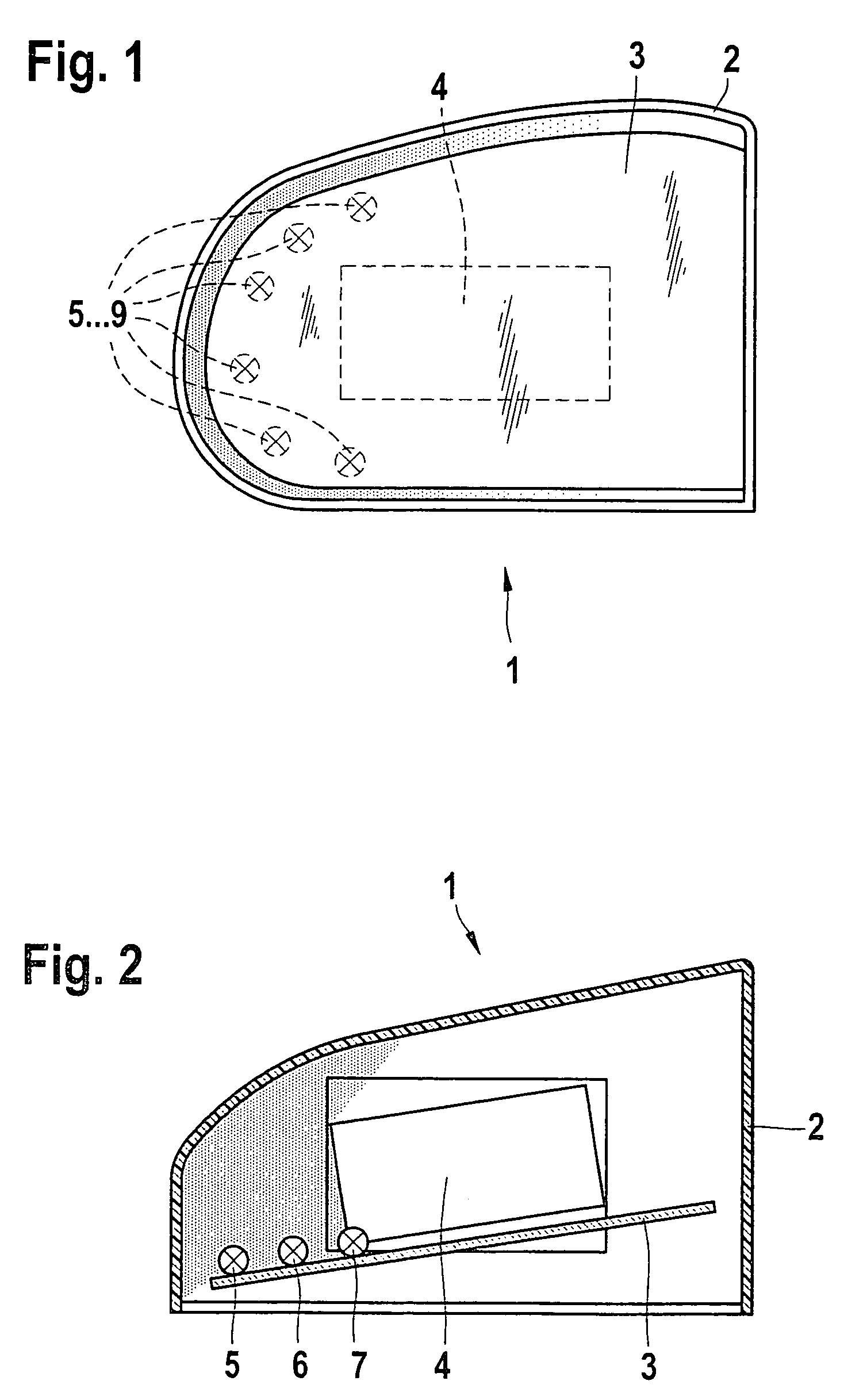
[0010]FIG. 1 shows an outside rear-view mirror 1 that includes a mirror housing 2, a mirror glass 3, a positioning motor 4 for adjusting the mirror as well as lighting elements 5 through 9. In the illustrated exemplary embodiment, the lighting elements are mounted, preferably by gluing, onto the mirror glass from the rear, i.e., on the side of the glass that is not visible to the driver. These lighting elements are activated to alert the driver in certain situations, in the preferred exemplary embodiment by a blind spot detection system, when the latter detects a traffic participant in the vehicle's blind spot. In this situation, the lighting elements are made to light up, alerting the driver to the danger by indirectly illuminating the mirror housing.

[0011]In the preferred exemplary embodiment, the lighting elements are mounted in the external area of the outside rear-view mirror on the side facing away from the motor vehicle. This illuminates at least this part of the inner mirror...


PUM


Abstract

Indicating device for a motor vehicle, having at least one lighting element that is mounted in the housing of a mirror, for example by gluing it onto the mirror glass from the rear, and which illuminates the housing interior, making it only indirectly visible to the driver.

Description

BACKGROUND INFORMATION[0001]In automotive engineering, there are a great many functions that operate indicators, for example, warning lights. One example of a function of this type is a blind spot detection system like the one described, for example, in unpublished German Patent Application No. 101 25 426.1, dated May 25, 2001. Using sensors, for example radar sensors, this detection system detects traffic participants in the blind spot zone and, if a traffic participant is detected in this zone, activates a warning light that is usually mounted internally on the A-pillar of the vehicle in the area of the outside rear-view mirror.[0002]Other functions that operate indicators are, for example, parking aids or similar devices that visualize the distance from a vehicle to the rear and / or activate a warning light when the distance drops below a minimum value.[0003]Due to their functions, indicators of this type must be designed so that the driver will not miss them in the particular sit...

Claims


Application Information

Patent Timeline
Patent Type & Authority Patents(United States)
IPC IPC(8): B60Q1/26B60R1/12
CPCB60Q1/2665B60R1/1207B60R2001/1215
Inventor HAAG, PETER
Owner ROBERT BOSCH GMBH
Why Eureka
Try Eureka