Embedded high temperature valve

a high-temperature valve and embedded technology, applied in the field of rockets and missiles, can solve the problems of high-temperature materials used to construct the attitude control valve, may be exposed to relatively high temperatures, and may affect and achieve the effect of not adversely affecting the overall weight of the rocket and missil

Inactive Publication Date: 2008-04-15
HONEYWELL INT INC
View PDF6 Cites 3 Cited by
  • Summary
  • Abstract
  • Description
  • Claims
  • Application Information

AI Technical Summary

Benefits of technology

[0008]The present invention provides a valve that may be used to direct the flow of high temperature propellant gas in rockets and missiles, and most notably strategic rockets and missiles, without adversely impacting the overall weight of the rockets and missiles.

Problems solved by technology

The attitude control valves that are used in guidance control systems, such as that described above, may be exposed to relatively high temperatures.
Although attitude control valves constructed of high-temperature materials, such as refractory metals, operate safely, reliably, and robustly, these valves do exhibit certain drawbacks.
However, in many instances the high-temperature materials used to construct the attitude control valves often have relatively high densities.
As a result, increasing the thickness of various portions of the valves can significantly increase the weight of the valve, and thus the overall weight of the rocket or missile, which can be highly undesirable.

Method used


Image

  • Embedded high temperature valve
  • Embedded high temperature valve
  • Embedded high temperature valve

Examples


Embodiment Construction

[0015]The following detailed description is merely exemplary in nature and is not intended to limit the invention or its application and uses. Furthermore, there is no intention to be bound by any theory presented in the preceding background or the following detailed description. In this regard, before proceeding with the detailed description, it will be appreciated that the present invention is not limited to use with a particular type or configuration of rocket motor, rocket, or missile, and it will be appreciated that the embodiments could also be used in conjunction with any one of numerous other systems, devices, or components that may be otherwise exposed to hot gas.

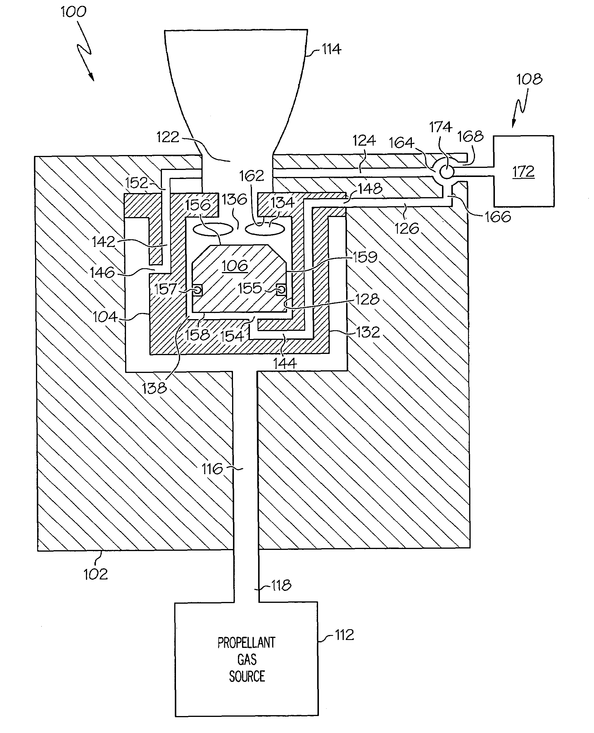
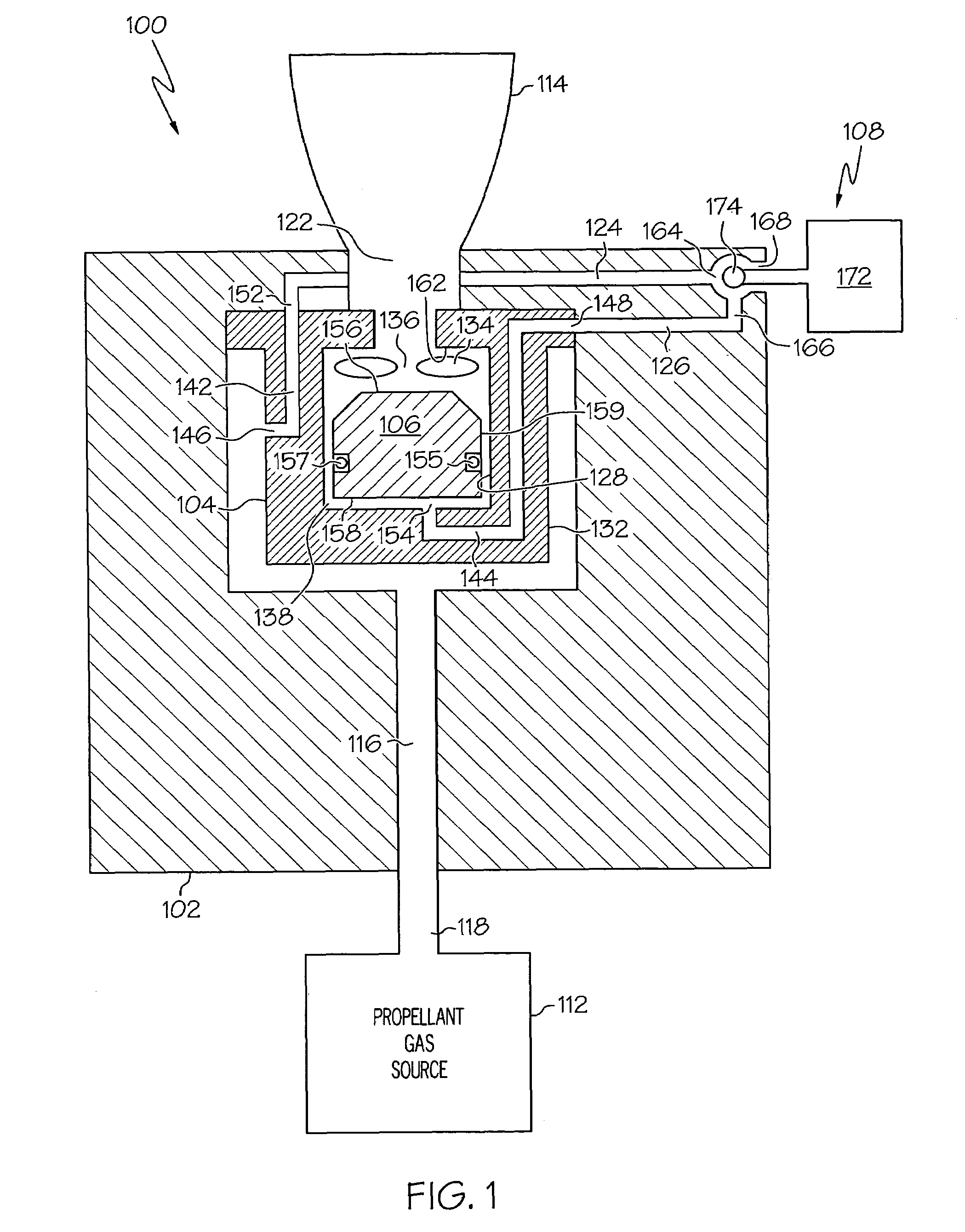
[0016]Turning now to the description and with reference first to FIG. 1, a simplified cross section view of an embodiment of a valve assembly 100 is shown. The valve assembly 100 includes an outer vessel 102, a valve housing 104, a valve element 106, and a control valve 108, and is preferably used to control the fl...


PUM


Abstract

A high temperature valve for controlling gas flow includes an outer vessel, a valve housing, and a valve element. The valve housing is disposed at least partially within, and is at least partially surrounded by, a propellant gas flow passageway that is formed in the outer vessel, and the valve element is disposed within the valve housing. Because the gas flow passageway at least partially surrounds the valve housing, when gas is supplied to the gas flow passageway a compressive force, rather than a tensile force, is exerted on the valve housings.

Description

CROSS-REFERENCES TO RELATED APPLICATIONS[0001]This application claims the benefit of U.S. Provisional Application No. 60 / 565,571, filed Apr. 26, 2004.TECHNICAL FIELD[0002]The present invention relates to rockets and missiles and, more particularly, to a valve that may be used to direct the flow of high temperature propellant gas in rockets and missiles.BACKGROUND[0003]Many rockets and missiles include one or more solid rocket motors to generate thrust to achieve and / or maintain flight, and / or to control in-flight direction. A solid rocket motor may include, for example, a motor case and a main nozzle. Typically, the motor case defines a combustion chamber, in which propellant is loaded and combusted to generate high-energy propellant gas. The main nozzle is typically in fluid communication with the combustion chamber and thus receives the high-energy propellant gas. The main nozzle may include a convergent inlet section, a divergent outlet section, and an interposing main nozzle thr...

Claims


Application Information

Patent Timeline
Patent Type & Authority Patents(United States)
IPC IPC(8): F16K31/12
CPCF02K9/58F02K9/805
Inventor CHRISTENSEN, DONALD J.
Owner HONEYWELL INT INC
Why Eureka
Try Eureka