Drive-control system of electromotive vehicle and drive-control-method of electromotive vehicle

a technology of drive control system and electromotive vehicle, which is applied in the direction of propulsion parts, propulsion using engine-driven generators, process and machine control, etc. it can solve the problems of discomfort to the driver, vibration generated in the vehicle-drive-system cannot be quickly damped, and achieve the effect of quick damped and preventing discomfort to the driver

Active Publication Date: 2008-04-15
AISIN AW CO LTD
View PDF11 Cites 33 Cited by
  • Summary
  • Abstract
  • Description
  • Claims
  • Application Information

AI Technical Summary

Benefits of technology

[0010]The exemplary embodiment of the present invention addresses the problems of the conventional vehicle-drive-system, and provides a drive-control-system of the electromotive vehicle and a drive-control-method of the electromotive vehicle that can damp the vibration generated in the vehicle-drive-system, and can prevent discomfort to the driver.
[0014]The damping-control-process unit reduces the variable of the vibration generation by controlling the driving motor.
[0027]In this case, since the damping-control-process is performed such that the variable of the vibration generation is reduced when the damping-control-starting-condition is established, the vibration generated in the vehicle-drive-system can be quickly damped, and the discomfort to the driver can be prevented.

Problems solved by technology

However, in the conventional vehicle-drive-system, (JP-A-2002-12046), for example, when driving torque generated in the driving wheel for running the hybrid vehicle varies, or the engine is started or stopped, vibration is generated in the vehicle-drive-system, resulting in discomfort to a driver.
However, when the driving-motor-torque is controlled such that the vibration in the vehicle-driving-system is damped at any time, especially in steady running, high-frequency vibration is generated in a sensor output from a position sensor for detecting a rotor position of the driving motor due to noise, resulting in discomfort to the driver.
However, in this case, for example, when the driving torque varies, or the engine is started or stopped, the vibration generated in the vehicle-drive-system can not be quickly damped, resulting in discomfort to the driver.

Method used


Image

  • Drive-control system of electromotive vehicle and drive-control-method of electromotive vehicle
  • Drive-control system of electromotive vehicle and drive-control-method of electromotive vehicle
  • Drive-control system of electromotive vehicle and drive-control-method of electromotive vehicle

Examples


Embodiment Construction

[0043]Hereinafter, an exemplary embodiment of the invention is described in detail with reference to drawings. In this case, a hybrid vehicle as an electromotive vehicle is described.

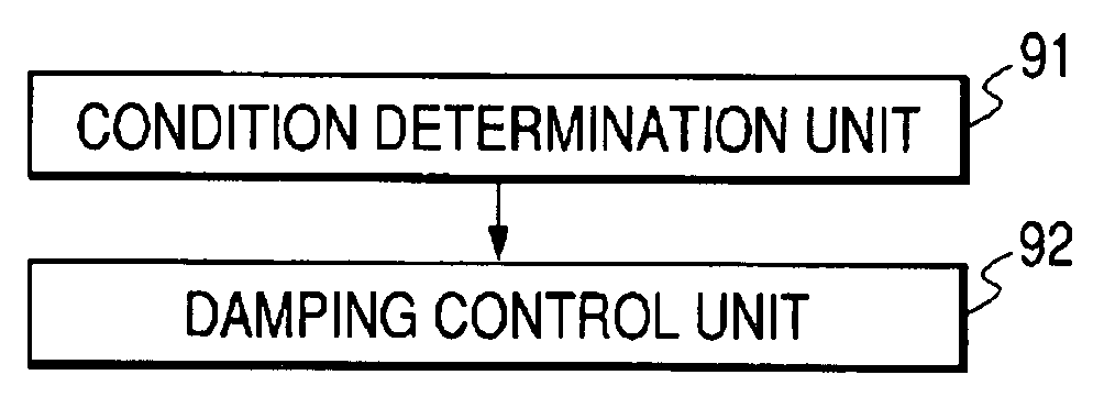
[0044]FIG. 1 is a functional block diagram of a drive-control-system of the electromotive vehicle consistent with an exemplary embodiment of the invention.

[0045]In FIG. 1, condition-determination-process unit 91 reads a vibration index as a factor causing vibration in the vehicle-drive-system, and determines whether the damping-control-starting-condition is established based on the vibration index. Damping-control-process unit 92 performs the damping-control-process such that the variable of the vibration generation is reduced when the damping-control-starting-condition is established.

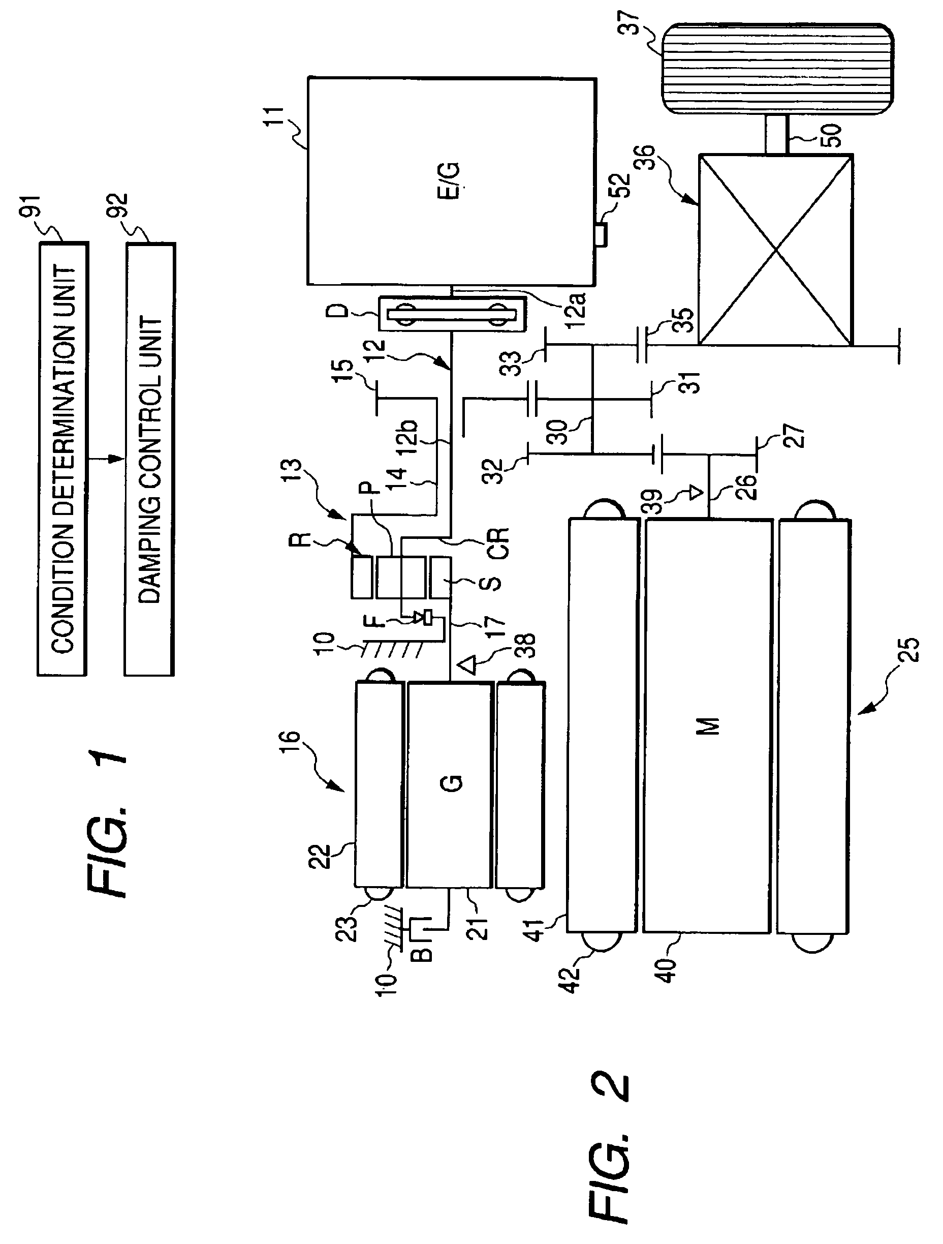
[0046]Next, the hybrid vehicle is described. FIG. 2 is a conceptual diagram of the hybrid vehicle consistent with an exemplary embodiment of the invention.

[0047]In FIG. 2, engine (E / G) 11 is a driving source arranged on a ...


PUM


Abstract

A drive-control-system of electromotive vehicle and drive-control-method of an electromotive vehicle. A system has a condition-determination-process unit that reads a vibration index as a factor causing vibration in the vehicle-drive-system, and determines whether a damping-control-starting-condition is established based on the vibration index, and a damping-control-process unit that performs a damping control process such that a variable of vibration generation is reduced when the damping-control-starting-condition is established.

Description

BACKGROUND OF THE INVENTION[0001]This application claims the priority of Japanese Patent Application No. 2004-025728 filed on Feb. 2, 2004, the specification, drawings and abstract thereof, are incorporated herein by reference in their entirety.[0002]1. Field of the Invention[0003]The present invention relates to a drive-control-system of an electromotive vehicle and a drive-control-method of the electromotive vehicle.[0004]2. Description of the Related Art[0005]Conventionally, a vehicle-drive-system mounted on a hybrid vehicle such as an electromotive vehicle, in which a part of engine-torque, that is torque of an engine is transmitted to a generator (generator motor) and the rest of the engine torque is transmitted to a driving wheel, has a planetary gear unit as a differential tuning gear having a sun gear, ring gear, and carrier. The sun gear is linked with the generator, the ring gear and a driving motor are linked with the driving wheel, the carrier is linked with the engine, ...

Claims


Application Information

Patent Timeline
Patent Type & Authority Patents(United States)
IPC IPC(8): B60L9/00B60W20/00B60K1/00B60K6/445B60K17/04B60L15/20B60L50/16B60W10/06B60W10/08F16H48/10
CPCB60K6/445B60W10/06B60W10/08B60W20/00B60L2240/423B60W2710/0661B60W2710/083Y02T10/6286Y02T10/7258Y02T10/642Y10S903/91Y02T10/6239Y02T10/62Y02T10/64Y02T10/72B60W10/22
Inventor HISADA, HIDEKIAOKI, KAZUOHASEGAWA, KAZUMA
Owner AISIN AW CO LTD
Why Eureka
Try Eureka