
Method and device for making mineral fiber felts

a mineral fiber and felting technology, applied in the field of felting formation, can solve the problems of not being able to improve other properties such as tear resistance, not being able to meet the needs of use, etc., and achieve the effect of reliable and simpl

Inactive Publication Date: 2008-04-08
SAINT-GOBAIN GLASS FRANCE
View PDF7 Cites 0 Cited by
  • Summary
  • Abstract
  • Description
  • Claims
  • Application Information

AI Technical Summary

Benefits of technology

[0021]The present invention advantageously consists of a reliable and simple solution which completely solves the abovementioned problem.
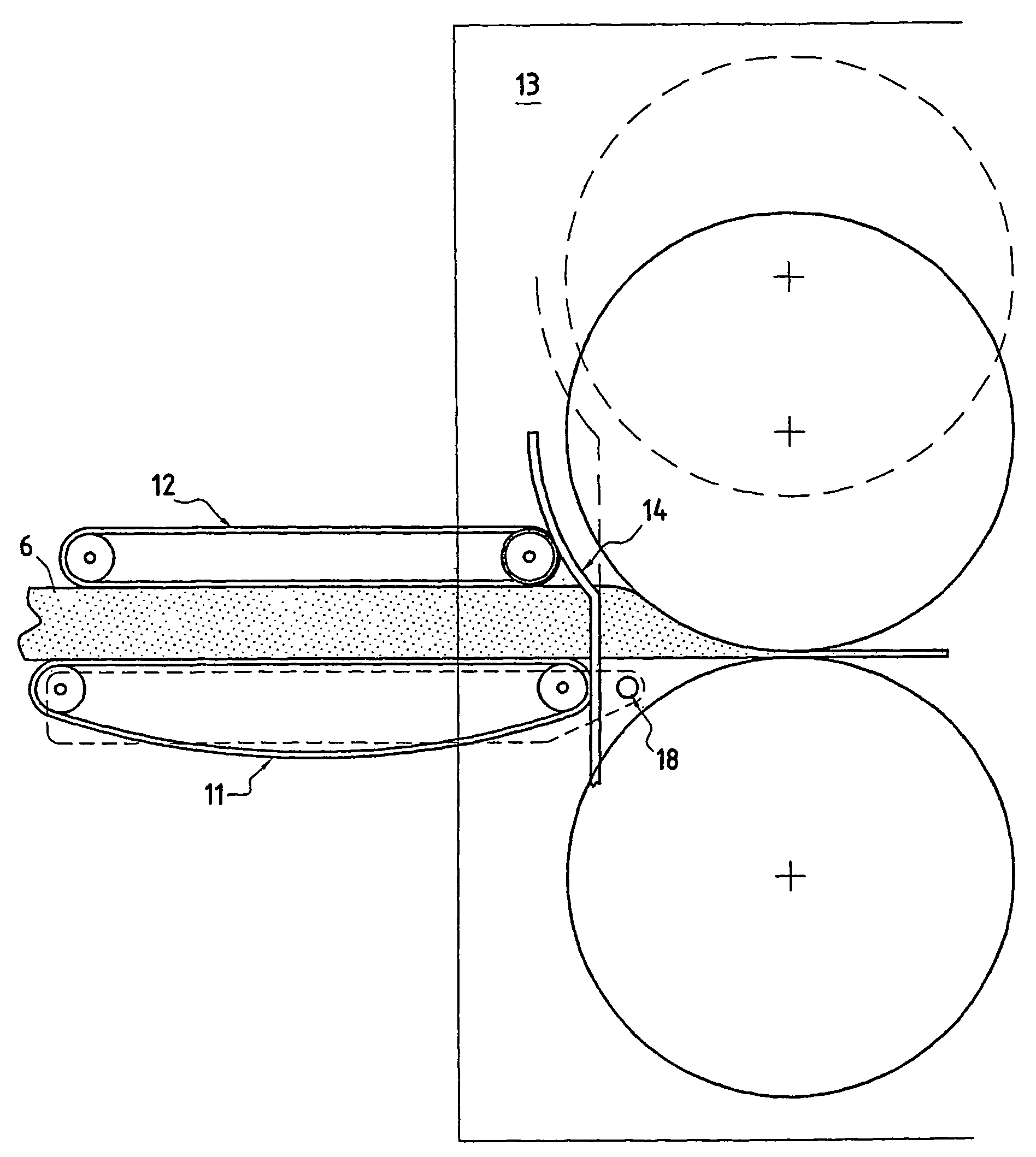
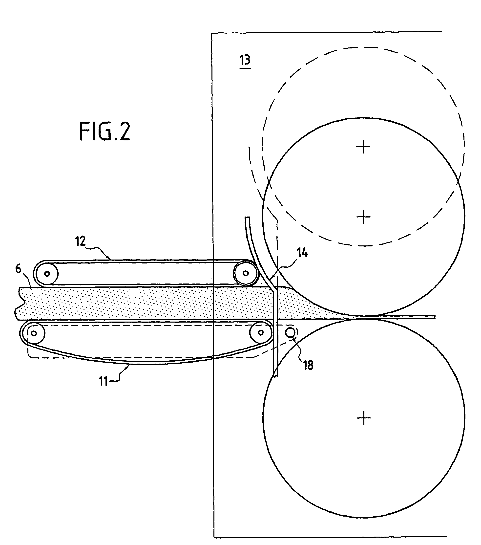
[0025]Specifically, the cam is rigidly linked to one element of the heat treatment means, said element being able to move vertically and / or horizontally. The horizontal movement makes it possible to compensate for the thermal expansions.
[0031]Characteristically, the process furthermore consists in preventing decompression of the fibers between the compression step and the heat treatment step, by means of a cam having a profile suitable for keeping a constant and minimum distance between the compression means and the heat treatment means.

Problems solved by technology

In addition to the insulating properties required very generally, it is also sometimes necessary for the products used to have very specific mechanical properties.
Forming felts by depositing fibers on the receiving conveyor or on a similar member results in an entanglement which is not uniform in all directions.
However, it will be understood that such a structure is not best suited when, for example, the product has to withstand compression or tearing in its thickness direction.
Besides the fact that the mass of fibers per unit area that can be deposited is limited, the build-up of fibers on the receiving member rapidly preventing the flow of gases and therefore preventing the felt from continuing to be formed properly, which does not allow other properties such as the tear resistance to be improved.
Due to the effect of the compression under the conditions envisaged, the felt forms corrugations.
However, this structure is to the detriment of the longitudinal tensile strength—the felt has a tendency to unfold—or to the flexural strength.
One problem associated with such manufacturing techniques resides in the homogeneity of the final felt and in particular in its surface homogeneity.
This is because cracks, fracture initiators and / or localized swellings are observed on the surface, these being defects which are negative in terms of the mechanical and thermal behavior, without mentioning the unattractive appearance of the assembly.
This problem is essentially created in the region between the conveyor belts and the crosslinking oven.
However, the slideways are then additional and fragile elements, the more so as they are placed in the immediate vicinity of the oven, which is hot.
In fact, this solution is not viable and the slideways pose more problems than they solve; this is why in practice this solution has been abandoned in favor of another solution, which constitutes the subject-matter of the present application.

Method used


Image

  • Method and device for making mineral fiber felts
  • Method and device for making mineral fiber felts
  • Method and device for making mineral fiber felts

Examples


Embodiment Construction

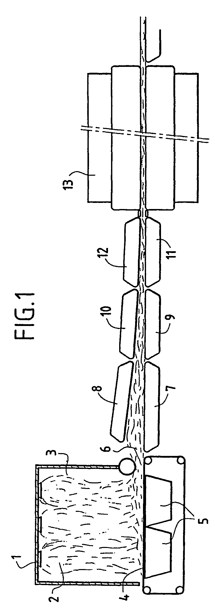
[0042]FIG. 1 shows the overall context in which the present invention may advantageously be employed.

[0043]This figure shows diagrammatically a line for manufacturing felts 6 formed from mineral fibers, also called rock wool or glass wool. In a known manner, such a line comprises one or more spinning devices 1 intended to form fibers 2 which are thrown off from the spinning device or devices 1 in a receiving chamber 3 at the base of which is placed a conveyor 4 onto which the fibers drop.

[0044]Preferably, one or more vacuum boxes 5 are located beneath the conveyor 4 so as to suck on and compact the fibers on the conveyor 4.

[0045]A web or felt 6 is thus formed; on leaving the chamber 3, the felt 6 is taken up between two conveyors 7, 8 intended to compress it in its thickness direction.

[0046]The felt 6 is then compressed longitudinally by passing between pairs of upstream conveyors 9, 10 and downstream conveyors 11, 12, the speeds of which are such that the speed of one pair, 11, 12,...


PUM

PropertyMeasurementUnit
thicknessaaaaaaaaaa
thicknessaaaaaaaaaa
distanceaaaaaaaaaa

Abstract

The subject of the invention is a unit for manufacturing felts (6) which are formed from crosslinked mineral fibers, comprising at least one pair of conveyors formed by a lower conveyor (11) and an upper conveyor (12) which are placed opposite each other and intended to compress said felt (6) in at least one direction, a means (13) for heat treating the felt (6) after it has passed through the conveyors (11, 12) comprising at least one means (14) placed between the conveyors (11, 12) and the heat treatment means (13), intended to prevent decompression of the felt (6) in this region, said means comprising at least one cam (14) having a profile suitable for keeping a constant and minimum distance between the conveyors (11, 12) and the heat treatment means (13), and in that at least one of the conveyors is rigidly connected to one element of the heat treatment means (13).

Description

BACKGROUND OF THE INVENTION[0001]1. Field of the Invention[0002]The invention relates to the formation of felts which are formed from mineral fibers and referred to by the generic names of glass wool, rock wool, etc.[0003]2. Discussion of the Related Art[0004]Conventionally, mineral fiber felts are made continuously by depositing the fibers on a conveyor, these being conveyed by gas streams. The conveyor retains the fibers and allows the gases to pass through them.[0005]Before they are deposited on the conveyor, the fibers are coated with a composition applied in liquid form and intended to bond the fibers together, so as to give the subsequently formed felt its cohesion. Composition is then crosslinked by a heat treatment carried out on the felt, which has been conditioned beforehand to the desired thickness and density.[0006]In addition to the insulating properties required very generally, it is also sometimes necessary for the products used to have very specific mechanical proper...

Claims


Application Information

Patent Timeline
Patent Type & Authority Patents(United States)
IPC IPC(8): B29C43/22B29C43/46B29C43/48D04H17/10D04H1/08D04H1/4209D04H1/4218D04H1/54D04H1/552D04H1/64D04H1/70
CPCD04H1/4209D04H1/4218D04H1/54D04H1/552D04H1/64D04H1/70D04H1/4226D04H17/10D04H1/08
Inventor BOUQUET, FRANCOISBLANDIN, YANNICKDEBOUZIE, ALAIN
Owner SAINT-GOBAIN GLASS FRANCE
Learn More