
Watch including at least two regulating systems

a technology of regulating system and watch, applied in the direction of clock driving mechanism, pre-selected time interval producing apparatus, instruments, etc., can solve the problems of loss of efficiency in additional gear trains, principle failure to meet with success, and fitted to extremely thick watches

Active Publication Date: 2008-04-01
MONTRES BREGUET
View PDF25 Cites 23 Cited by
  • Summary
  • Abstract
  • Description
  • Claims
  • Application Information

AI Technical Summary

Benefits of technology

The present invention is about a new mechanical movement for a watch that improves its working. It includes at least two regulating systems, each with a mechanical oscillator and an escapement, mounted on a common support and connected to a common time display device via a differential gear. The movement is characterized by the use of a differential gear to connect the barrel or going train of each sub-assembly to the display, which does not affect the efficiency of the going trains. The barrels are connected to each other and to a winding device by a differential winding gear, which compensates for the winding between them. The common support of the regulating systems can be fixed or formed by a rotating plate, which adds compensation for the effects of gravity on unbalance as in a tourbillon. The regulating systems mounted on the rotating plate can be two tourbillon systems, which further improves the regularity of working of the watch.

Problems solved by technology

These constructions constitute a remarkable feat, but they occupy a spherical space and thus can only be fitted to an extremely thick watch.
This principle did not meet with success, probably because the theoretical gains were offset by losses in efficiency in the additional gear trains, in particular in the differential gear.

Method used


Image

  • Watch including at least two regulating systems
  • Watch including at least two regulating systems
  • Watch including at least two regulating systems

Examples


Embodiment Construction

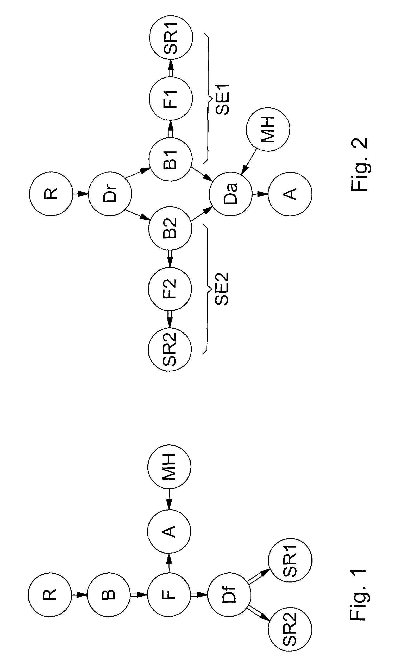
[0022]In order to explain more clearly how the example described hereinafter works, the block diagrams of FIGS. 1 and 2 respectively show a watch movement according to CH Patent No. 156 801 and a preferred embodiment of the invention. Reference will be made to the following legend:

[0023]

ADisplayB, B1, B2Barrel springDfGoing train differentialDrWinding train differentialDaDifferential display gearF, F1, F2Going trainMHTime-settingSR1, SR2Regulating systemRWinding

[0024]In these diagrams, the single arrows represent gear trains with no energy transmission to the regulating systems, whereas the double arrows represent gear trains with energy transmission to the regulating systems. It will also be noted that, in these diagrams, the symbol SR can represent both an ordinary mechanical regulating system and a rotating regulating system, particularly a tourbillon.

[0025]In the diagram of FIG. 1, the top part comprising the elements R, B, F, A and MH is the same as for a conventional clockwork...


PUM


Abstract

The invention concerns a watch with a mechanical movement of the type comprising at least two regulating systems (SR1, SR2) each including a mechanical oscillator and an escapement. The movement includes as many sub-assemblies (SE1, SE2) as there are regulating systems, each of said sub-assemblies including a regulating system (SR1, SR2), a barrel (B1, B2) and a going train transmitting energy from the barrel to the regulating system inside the sub-assembly. A differential display gear (Da) connects the barrel or the going train of each sub-assembly to the display (A) to average out the rate of the two sub-assemblies. In a preferred embodiment, the two sub-assemblies are mounted on a common rotating support (5) and their regulating systems are tourbillons which make an orbital movement about the center of the watch dial.

Description

[0001]This application claims priority from European Patent Application No. 05006849.3 filed Mar. 30, 2005, the entire disclosure of which is incorporated herein by reference.BACKGROUND OF THE INVENTION [0002]The present invention concerns mechanical clockwork movements, in particular in watches, and it concerns certain arrangements for reducing the errors in isochronism caused by imperfections in the regulating system of the watch.[0003]The tourbillon invented two centuries ago by Abraham-Louis Breguet is a device that reduces errors in isochronism resulting from effects produced particularly by gravity on the regulating organs of the watch, because of the inevitable faulty poising of such organs. As the oscillator and the escapement are mounted in a carriage or cage which rotates about an axis parallel to the axis of the sprung balance assembly, the gravity component that is exerted in the perpendicular plane to these axes performs a continuous rotation in relation to the organs, ...

Claims


Application Information

Patent Timeline
Patent Type & Authority Patents(United States)
IPC IPC(8): G04F5/00
CPCG04B1/12G04B17/285
Inventor ZAUGG, ALAIN
Owner MONTRES BREGUET
Learn More