
Vibratory measurement transducer

a technology of vibration-type measurement and transducer, which is applied in the direction of mass flow measurement devices, measurement devices, instruments, etc., can solve the problems of significant imbalances in measurement transducers, large installed mass, and large measurement errors

Active Publication Date: 2008-04-01
ENDRESS HAUSER FLOWTEC AG
View PDF10 Cites 67 Cited by
  • Summary
  • Abstract
  • Description
  • Claims
  • Application Information

AI Technical Summary

Benefits of technology

This approach allows for the realization of vibration-type measurement transducers with measurement accuracy of 99.8% or more, suitable for large nominal diameters and high mass flow rates, while maintaining economic and manageable installed masses.

Problems solved by technology

Investigations on vibratory measurement transducers having two, mutually parallel, curved flow tubes, such as are described e.g. in U.S. Pat. No. 6,711,958 or U.S. Pat. No. 6,308,580, have shown, however, that, despite a largely symmetrical construction with reference to an imaginary central plane of the measurement transducer extending between the two curved central tube segments of the flow tubes, alternating imbalances can be produced in significant measure in the rhythm of the wanted oscillation frequency and, consequently, associated disturbance oscillations can be coupled out into the connected pipeline.
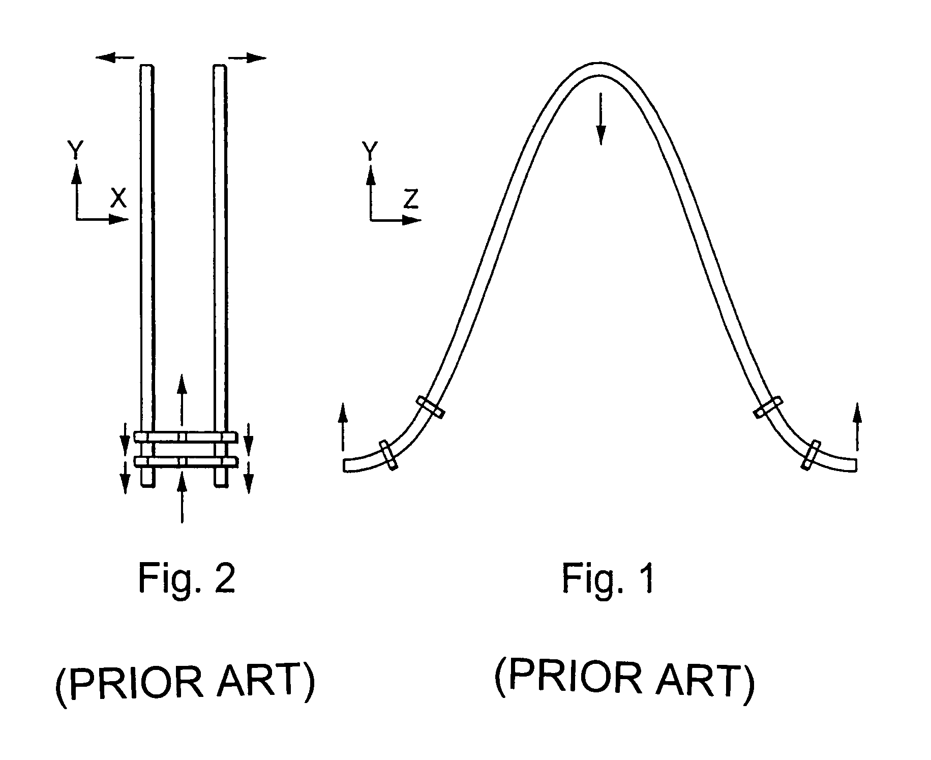
Further investigations have, moreover, shown that, in the case of measurement transducers of the described type, especially those with V-shaped or trapezoidally bent, flow tubes and / or with flow tubes whose tube diameters amount to 80 mm or more, besides such forces coming mainly from the acceleration of moved masses, to an increasing degree, also clamping forces can also lead to significant imbalances in the measurement transducer, such as are dependent on an asymmetric deformation of the transducer housing stemming from an instantaneous deflection of the flow tubes.
However, a special problem connected with such a measure is that, in the case of measurement transducers of large nominal diameter, the installed mass is already very high.
Thus, in the case of measurement transducers of large nominal diameter, the possibilities for sufficient stiffening of the transducer housing by increased material thicknesses must be considered as very limited, at least for the desired application of proven materials, especially stainless steel.

Method used


Image

  • Vibratory measurement transducer
  • Vibratory measurement transducer
  • Vibratory measurement transducer

Examples


Embodiment Construction

[0047]While the invention is susceptible to various modifications and alternative forms, exemplary embodiments thereof have been shown by way of example in the drawings and will herein be described in detail. It should be understood, however, that there is no intent to limit the invention to the particular forms disclosed, but on the contrary, the intention is to cover all modifications, equivalents, and alternatives falling within the spirit and scope of the invention as defined by the intended claims.

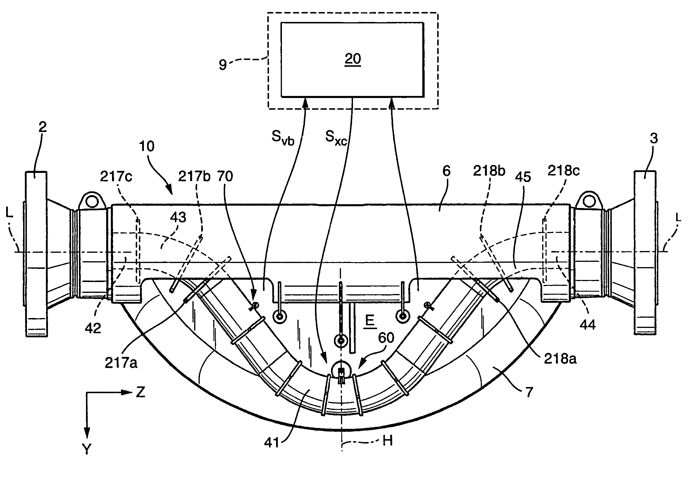
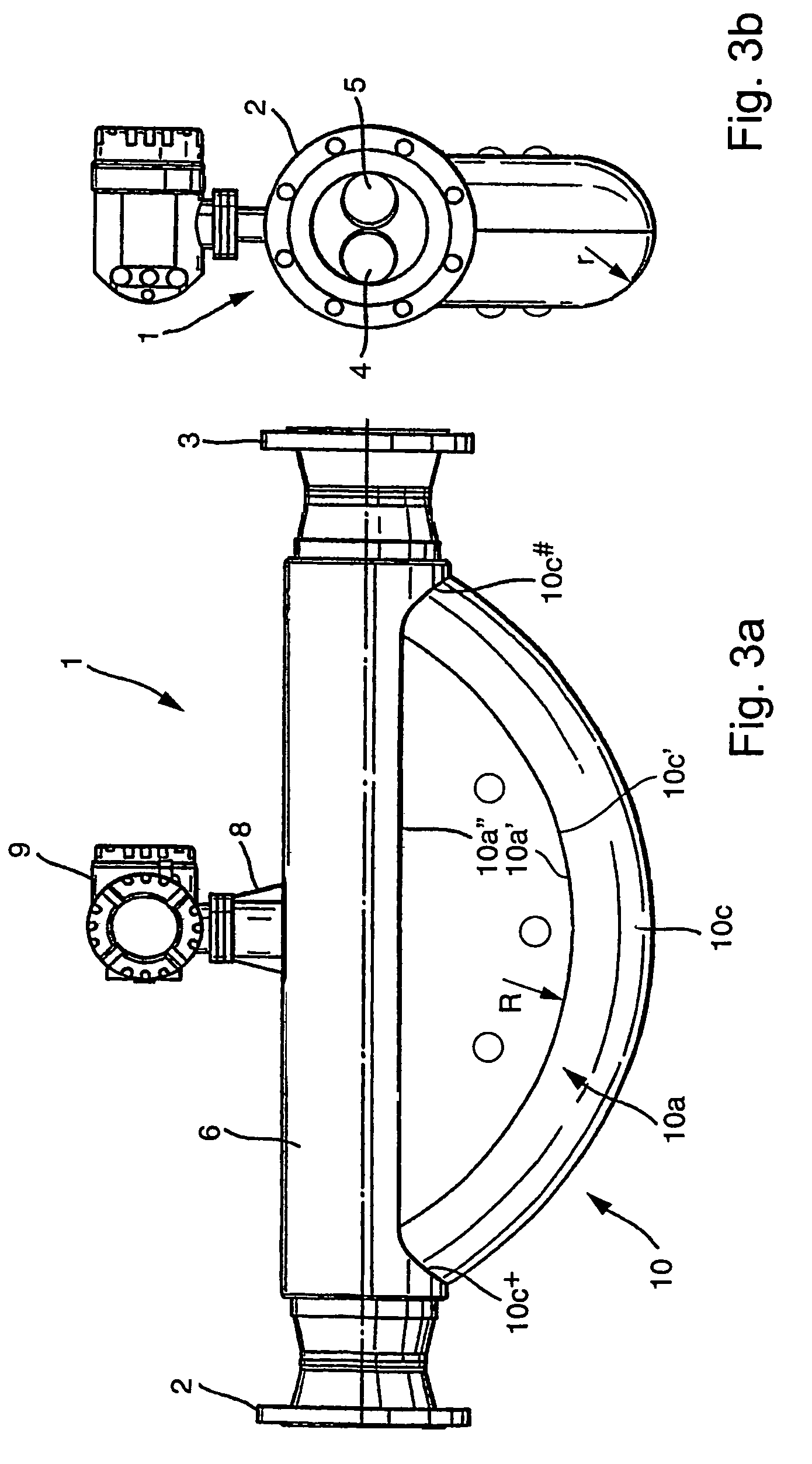
[0048]FIGS. 3a, b show an inline measuring device 1, especially one constructed as a Coriolis mass flow and / or density measuring device, serving, for example, for registering a mass flow rate m of a medium flowing in a pipeline (not shown) and for mapping such into a mass flow rate, measured value Xm instantaneously representing this mass flow rate. The medium can be practically any flowable substance, for example a powder, a liquid, a gas, a vapor, or the like. Alternatively, or in s...


PUM


Abstract

The measurement transducer includes a transducer housing, which exhibits a plurality of natural oscillation modes, as well as at least one first flow tube held oscillatably in the transducer housing, vibrating at least at times, and conveying at least a portion of the medium to be measured. Additionally, the measurement transducer includes an electromechanical, especially electrodynamic, exciter arrangement acting on the at least one flow tube for producing and / or maintaining mechanical oscillations of the at least one flow tube, and a sensor arrangement reacting to movements of the flow tube, especially bending oscillations, for producing at least one oscillation measurement signal representing oscillations of the flow tube. Additionally, for improving the oscillation properties and, consequently, also the measurement accuracy of the measurement transducer, at least three coupling elements are provided for connecting the first and second flow tubes together at the inlet end, as well as at least three coupling elements for connecting the first and second flow tubes together at the outlet end. By using at least six coupling elements, it is possible to produce vibration-type measurement transducers of high measuring accuracy even at large nominal diameters of more than 150 mm, especially also while largely maintaining already established and proven forms of construction.

Description

FIELD OF THE INVENTION[0001]The invention relates to a vibration-type measurement transducer for measuring a flowable medium, especially a gas, liquid, powder or other flowable substance, conveyed in a pipeline.BACKGROUND OF THE INVENTION[0002]In the technology of process measurements and automation, physical parameters, such as e.g. mass flow rate, density and / or viscosity, of a medium flowing in a pipeline are often measured using inline measuring devices, which include a vibratory measurement transducer, through which the medium flows, and a measurement and operating circuit connected thereto, for effecting reaction forces in the medium, such as e.g. Coriolis forces corresponding to the mass flow rate, inertial forces corresponding to the density of the medium and / or frictional forces corresponding to the viscosity of the medium, etc., and for producing, derived from these forces, measurement signals respectively representing mass flow rate, density and viscosity.[0003]Such measu...

Claims


Application Information

Patent Timeline
Patent Type & Authority Patents(United States)
IPC IPC(8): G01F1/84
CPCG01F1/8409G01F1/8413G01F1/8477
Inventor ANKLIN-IMHOF, MARTINSCHUETZE, CHRISTIAN
Owner ENDRESS HAUSER FLOWTEC AG
Learn More