
Method and apparatus for CRZ-DQPSK optical signal generation

a technology of optical signal and apparatus, applied in the field of optical communication, can solve the problems of increasing the complexity and cost of the transmitter, and the scheme cannot be used for the generation of rz-dpsk signals, and achieve the effects of reducing loss, reducing power consumption, and cost-effective and compact design

Inactive Publication Date: 2008-03-18
ALCATEL LUCENT SAS
View PDF6 Cites 13 Cited by
  • Summary
  • Abstract
  • Description
  • Claims
  • Application Information

AI Technical Summary

Benefits of technology

This approach results in cost-effective, compact, and low-power CRZ-DPSK signal generation with improved tolerance to modulator bandwidth limitations and reduced self-phase-modulation noise, maintaining performance even under under-driven conditions.

Problems solved by technology

However, such a scheme cannot be used for the generation of RZ-DPSK signals because it is not capable of generating the three states, ‘1’, ‘0’, and ‘−1’, in the optical field domain, of an RZ-DPSK signal.
However, such a scheme requires the use of an additional phase modulator to introduce chirp into the signal, which increases the complexity and cost of the transmitter.

Method used


Image

  • Method and apparatus for CRZ-DQPSK optical signal generation
  • Method and apparatus for CRZ-DQPSK optical signal generation
  • Method and apparatus for CRZ-DQPSK optical signal generation

Examples


Embodiment Construction

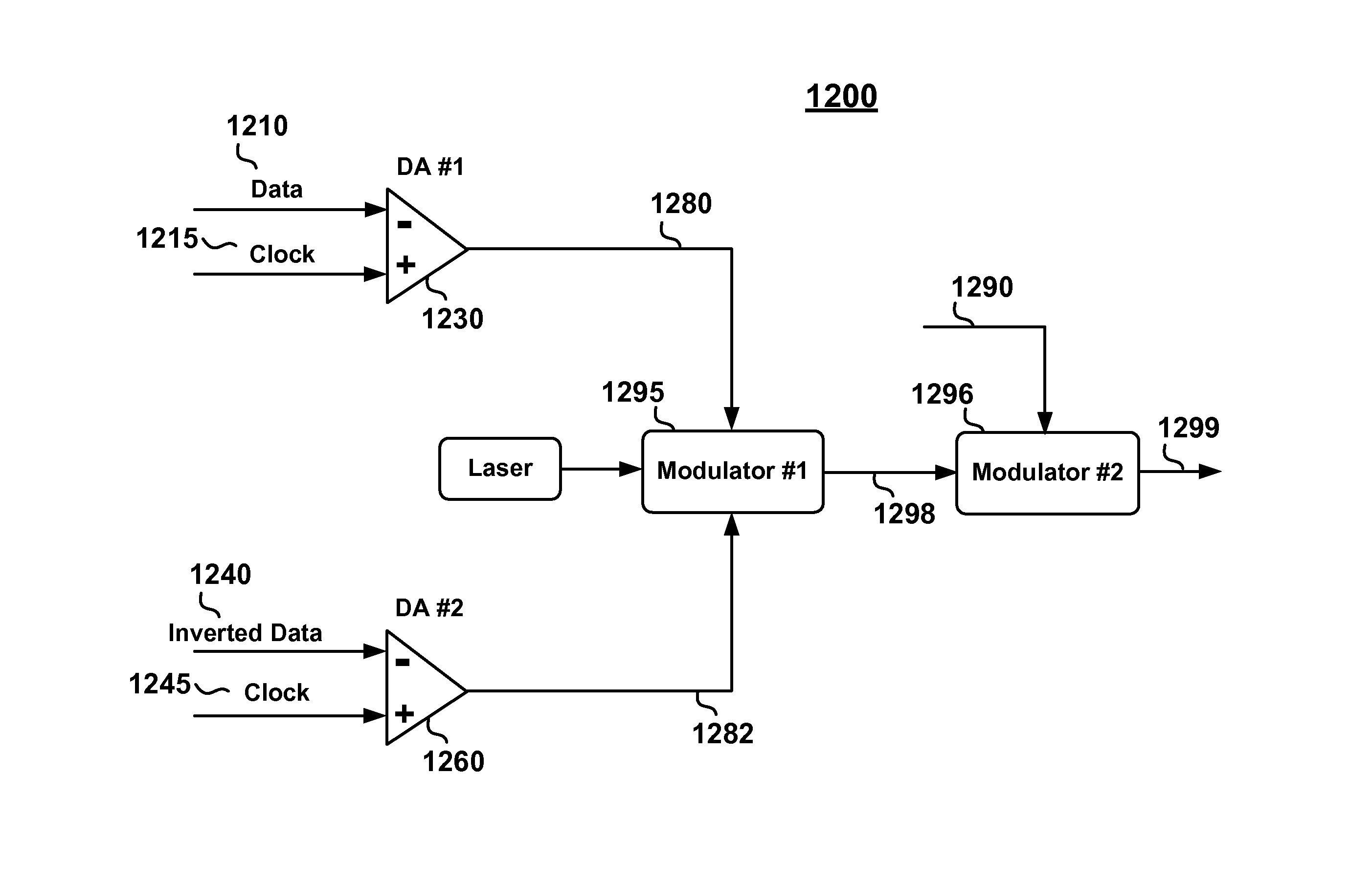
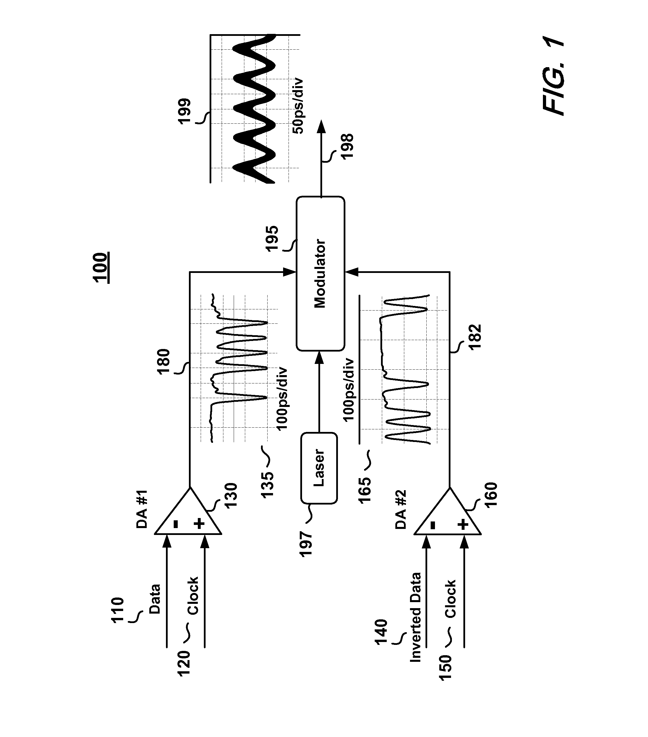
[0023]A CRZ-DPSK optical signal generator apparatus 100 of one embodiment of the invention is shown in FIG. 1. A data signal 110 and a sinusoidal first clock signal 120 are input into a differential amplifier (DA #1) 130. The data signal 110 contains differentially encoded data and has the same data rate as the first clock signal 120. The DA #1130 operates as a comparator to produce a first electronic “2-level” RZ formatted drive signal 180 (referred to hereinafter as the first RZ drive signal 180 and illustrated in the inset plot 135 of FIG. 1).

[0024]Those skilled in the art can appreciate that the data signal 110 and the first clock signal 120 are logically combined (e.g. by a logic AND operation) using the DA #1130. As used herein, a “2-level” signal refers to a signal having two distinct states (or voltages), one representing logic “1's” and the other representing logic “0's”.

[0025]Referring again to FIG. 1, the inverse of the data signal 110 (inverted data signal 140) and a sec...


PUM


Abstract

Apparatus and methods for generating chirped return-to-zero (CRZ) differential quadrature phase-shift keyed (DQPSK) optical signals using a single modulator driven by synchronous return-to-zero (RZ) drive signals to achieve simultaneous RZ pulse formatting and chirped DQPSK data modulation.

Description

CROSS-REFERENCE TO RELATED APPLICATION[0001]This application relates to a co-pending application entitled “Method And Apparatus For RZ-DPSK Optical Signal Generation” filed May 28, 2004.FIELD OF THE INVENTION[0002]The present invention relates generally to the field of optical communications, and more specifically to an apparatus and method for generating chirped return-to-zero (CRZ) differential phase-shift-keyed (DPSK) optical signals.BACKGROUND OF THE INVENTION[0003]The return-to-zero (RZ) pulse format for optical signals is known to offer performance advantages such as high receiver sensitivity and high immunity to inter-symbol interference as compared to non-return-to-zero (NRZ) formats. DPSK optical transmission has also been found to provide performance advantages when coupled with balanced detection, such as superior receiver sensitivity, high tolerance to some major nonlinear effects in high-speed transmissions, and high tolerance to coherent crosstalk. RZ-DPSK has accordin...

Claims


Application Information

Patent Timeline
Patent Type & Authority Patents(United States)
IPC IPC(8): H04B10/04H04B10/12
CPCH04B10/25137H04B10/505H04B10/5051H04B10/5053H04B10/5162H04B10/5561
Inventor KAO, YUAN-HUALIU, XIANG
Owner ALCATEL LUCENT SAS
Learn More