
System, method, and apparatus for distributing air in a blade server

a technology of blade servers and air distribution, applied in the field of computer servers and computer systems, can solve the problems of occupying huge amounts of expensive floor space, affecting the efficiency of cooling systems, and affecting the performance of cooling systems,

Active Publication Date: 2008-03-18
LENOVO GLOBAL TECH INT LTD
View PDF12 Cites 38 Cited by
  • Summary
  • Abstract
  • Description
  • Claims
  • Application Information

AI Technical Summary

Benefits of technology

The system effectively maintains consistent airflow and cooling across blades, preventing airflow starvation and enhancing the cooling capacity of blades, even when blades are removed or added, thereby improving performance and extending component lifespan.

Problems solved by technology

For a large organization, the storage racks can number in the hundreds and occupy huge amounts of expensive floor space.
Also, because the components are generally free standing components (i.e., they are not integrated), resources such as disk drives, keyboards, and monitors cannot easily be shared.
As cooling needs continue to increase, current cooling solutions suffer from problems in some situations.
When this happens, the slots adjacent to the empty slots will be starved of their required airflow and blade temperature will rise, potentially causing performance degradation, reduction of lifetime, or failure of components.
Another problem with current cooling solutions is that cooling air only enters the blades from the front.
For some high performance blades, certain components such as hard drives and memory may suffer from inadequate cooling when only traditional front-to-back cooling is offered because of the blade configuration and their particular needs.

Method used


Image

  • System, method, and apparatus for distributing air in a blade server
  • System, method, and apparatus for distributing air in a blade server
  • System, method, and apparatus for distributing air in a blade server

Examples


Embodiment Construction

[0022]The following is a detailed description of example embodiments of the invention depicted in the accompanying drawings. The example embodiments are in such detail as to clearly communicate the invention. However, the amount of detail offered is not intended to limit the anticipated variations of embodiments; but, on the contrary, the intention is to cover all modifications, equivalents, and alternatives falling within the spirit and scope of the present invention as defined by the appended claims. The detailed descriptions below are designed to make such embodiments obvious to a person of ordinary skill in the art.

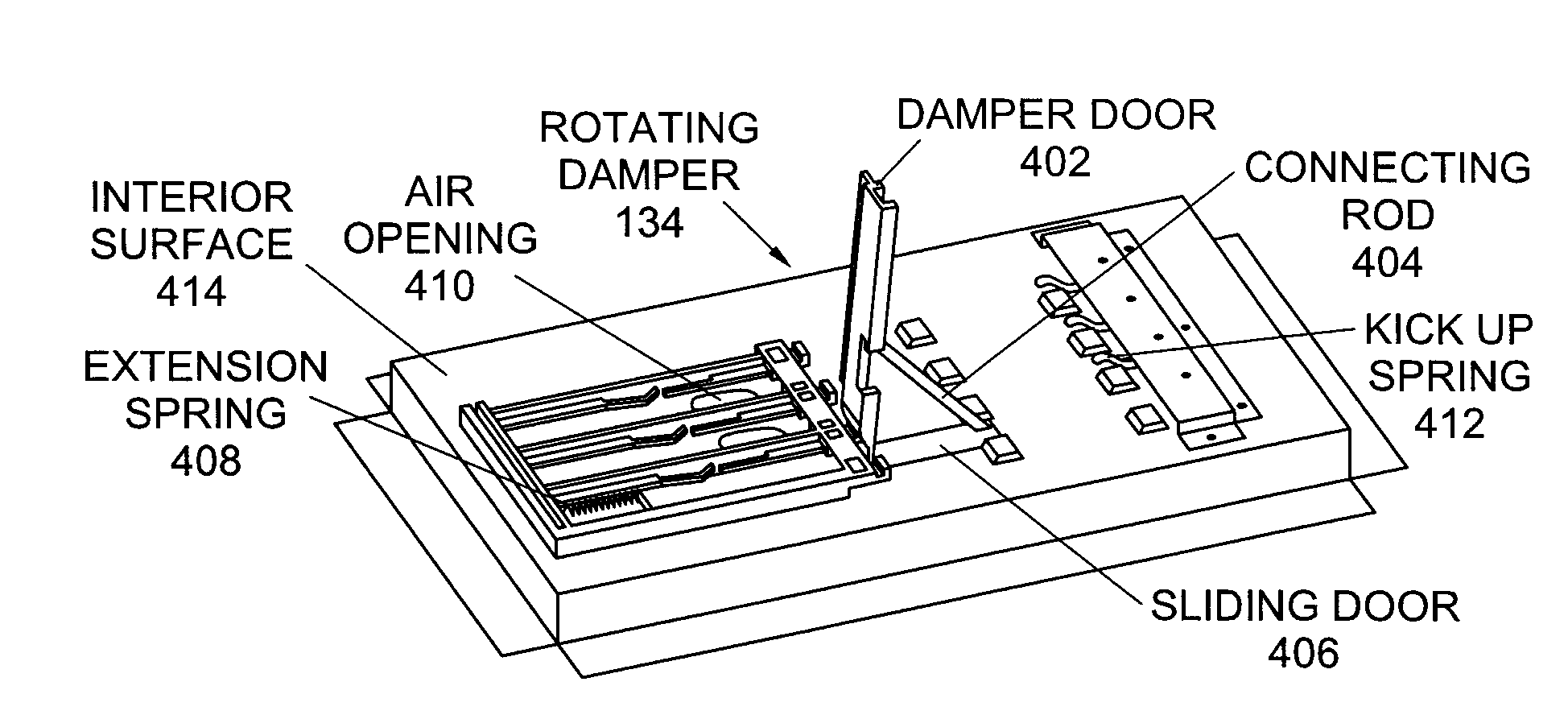
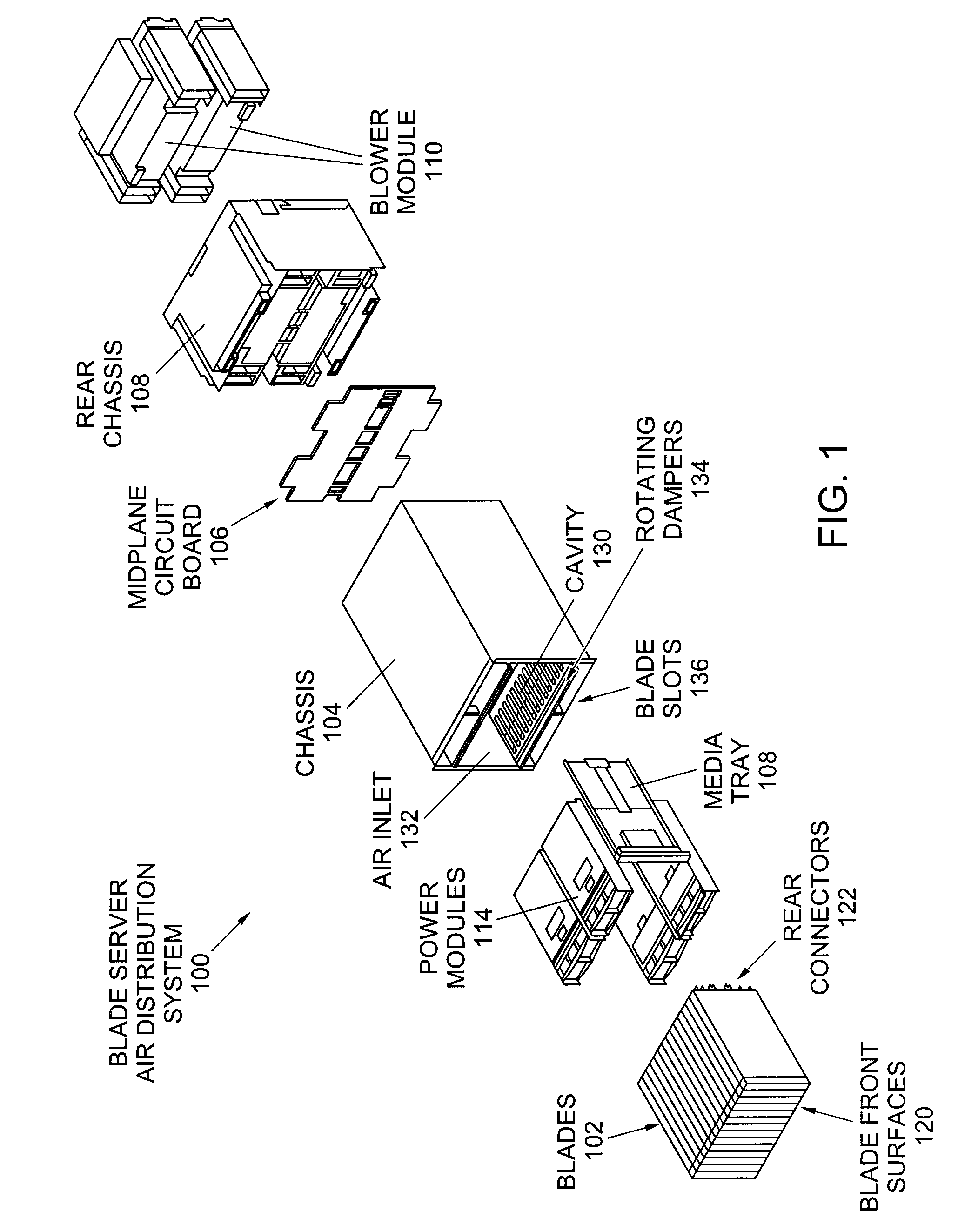
[0023]A system, method, and apparatus for distributing air in a blade server are disclosed. Embodiments may include a rotating damper apparatus for a blade server air distribution system having a damper door, a sliding door, and a connecting rod. The damper door may be rotatably attached to a blade server having a plurality of blade slots for receiving a blade and may...


PUM


Abstract

A system, method, and apparatus for distributing air in a blade server are disclosed. Embodiments may include a rotating damper having a damper door, sliding door, and connecting rod. The damper door may be rotatably attached to a blade server having a plurality of blade slots for receiving blades and may rotate between a blocking position and a flat position, where the damper door impedes air through a blade slot when in the blocking position. The sliding door may move between an open position and a closed position, where the sliding door allows airflow through an air opening while in the open position and blocks airflow through the air opening while in the closed position. A further embodiment may include an extension spring to apply a pulling force to the sliding door and a kick up spring to apply a pushing force to the damper door in the flat position.

Description

FIELD OF INVENTION[0001]The present invention generally relates to the field of computer servers and computer systems, such as a blade server with a chassis and a number of interconnected blades. More particularly, the present invention relates to a system, method, and apparatus for distributing air in a blade server.BACKGROUND[0002]In today's environment, a server computer system often includes several components, such as the server itself, hard drives, or other peripheral devices. These components are generally stored in racks. For a large organization, the storage racks can number in the hundreds and occupy huge amounts of expensive floor space. Also, because the components are generally free standing components (i.e., they are not integrated), resources such as disk drives, keyboards, and monitors cannot easily be shared. Blade servers have been developed to bundle the server computer system described above into a compact operating unit. A blade server may be a high-density, rac...

Claims


Application Information

Patent Timeline
Patent Type & Authority Patents(United States)
IPC IPC(8): H05K7/20G06F1/20H05K5/00
CPCH05K7/1445H05K7/20736
Inventor HENRY, MATTHEW S.JENSEN, DAVID J.LEWIS, SETH D.SMITH, PETER A.
Owner LENOVO GLOBAL TECH INT LTD
Learn More