Rolled coned manufacturing apparatus
a technology of rolling cones and manufacturing apparatuses, which is applied in the direction of manufacturing tools, containers for flexible objects, special goods baking, etc., can solve the problems of poor rolling cones, unavoidable axes of respective halves,
- Summary
- Abstract
- Description
- Claims
- Application Information
AI Technical Summary
Benefits of technology
Problems solved by technology
Method used
Image
Examples
embodiment 1
[0035]An embodiment of the present invention is explained below referring to figures. The present invention is not limited to this embodiment.
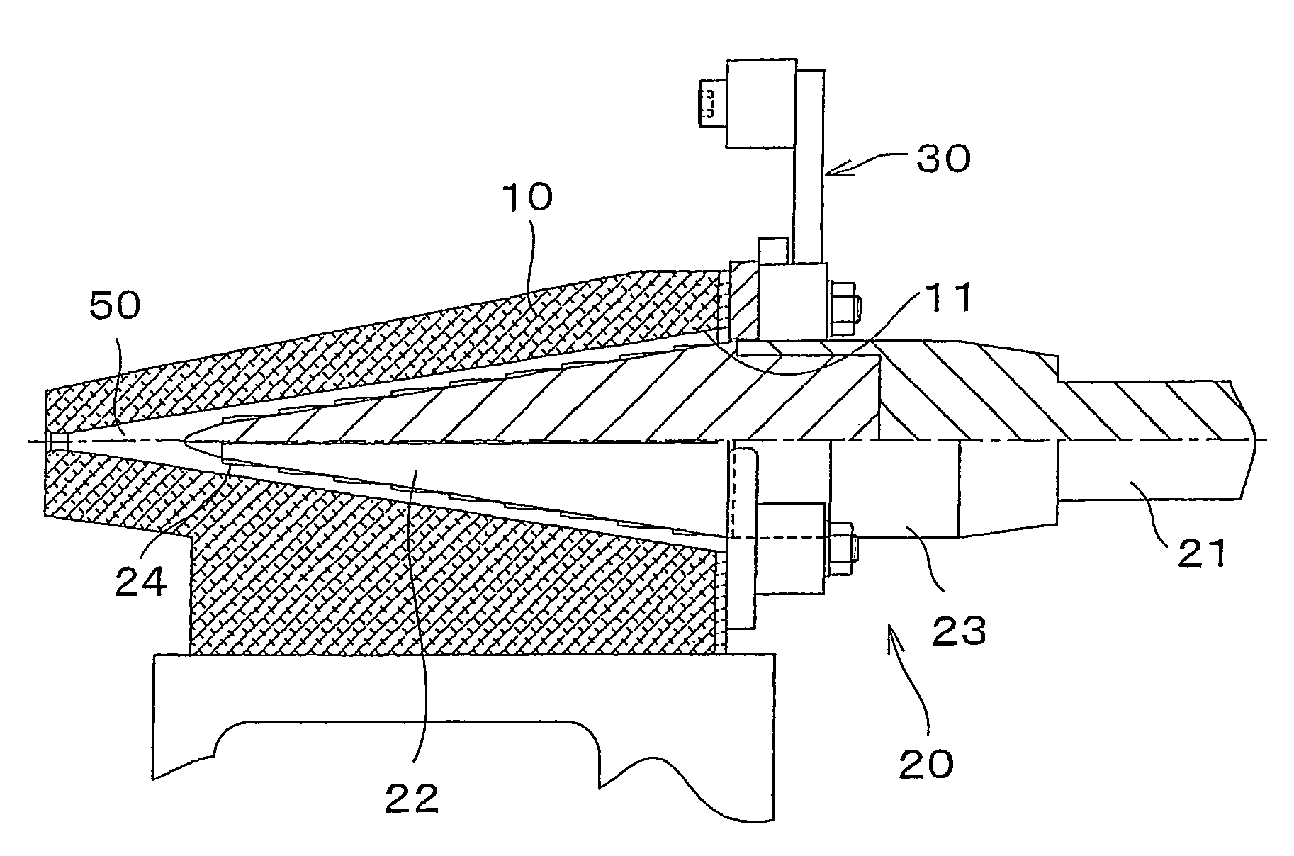
[0036]A rolled cone manufacturing apparatus in accordance with the present invention makes rolled cones in such a manner that a material sheet for baked confectionery is molded, (a first molding), and then the material sheet is rolled up using a mold made up of a concave half and a convex half (a second molding). Especially, the apparatus has supporting means that rotatably supports a spindle shaft of the convex half so that the respective axes of the convex half and the concave half are aligned with each other.
[0037]The above supporting means can be opened and closed, and supports and pushes an outer periphery of a part of the convex half protruding from the concave half onto the axis on at least three points in closed condition. For example, a loop-shaped member is preferably used in this embodiment.
[0038]In this embodiment, as shown in FIG....
embodiment 2
[0100]Another embodiment of the present invention is explained below referring to figures. The present invention is not limited to this embodiment. For convenience of explanation, the same number is shown for the member having the same function as the member used in the above embodiment 1 with the explanation left out.
[0101]In the embodiment 1, the supporting means is a loop-shaped member as the toggle-jointed link 30, but the present invention is not limited to this. The supporting means need not have a loop shape. In this embodiment, an openable and closable scissors-shaped member is exemplified as the toggle-jointed link 30.
[0102]More particularly, the rolled cone manufacturing apparatus in accordance with the present invention has the same structure as that of the embodiment 1. As schematically shown in FIG. 8, the supporting means is the scissors-shaped member 60 pinching an outer periphery of the convex half 20.
[0103]In the example shown in FIG. 8, the scissors-shaped member 6...
embodiment 3
[0108]Still another embodiment of the present invention is explained below referring to figures. The present invention is not limited to this embodiment. For convenience of explanation, the same number is shown for the member having the same function as the member used in the above embodiment 1 or 2 with the explanation left out.
[0109]In the above embodiments 1 and 2, the supporting means pinches an outer periphery of the convex half 20 with the arm-shaped members, such as the toggle-jointed link 30 and the scissors-shaped member 60. The present invention is not limited to this structure, and arranged in such a manner that the cylindrical part 23 of the convex half 20 is pushed onto the axis on at least three points, by an openable / closable member. Descriptions are given in this embodiment by exemplifying supporting means which is arranged to be movable to contact on or detach from an outer periphery of the convex half 20 and also pushes the convex half 20 onto the axis in contact c...
PUM
| Property | Measurement | Unit |
|---|---|---|
| angle | aaaaa | aaaaa |
| plasticity | aaaaa | aaaaa |
| conical shape | aaaaa | aaaaa |
Abstract
Description
Claims
Application Information
 - R&D
- Intellectual Property
- Life Sciences
- Materials
- Tech Scout
- Unparalleled Data Quality
- Higher Quality Content
- 60% Fewer Hallucinations
Browse by: Latest US Patents, China's latest patents, Technical Efficacy Thesaurus, Application Domain, Technology Topic, Popular Technical Reports.
© 2025 PatSnap. All rights reserved.Legal|Privacy policy|Modern Slavery Act Transparency Statement|Sitemap|About US| Contact US: help@patsnap.com


