
Reconfigurable optical add/drop multiplexer

Inactive Publication Date: 2008-03-11
LUCENT TECH INC
View PDF14 Cites 37 Cited by
  • Summary
  • Abstract
  • Description
  • Claims
  • Application Information

AI Technical Summary

Benefits of technology

"The present invention provides a system method and apparatus for equalizing and add / dropping optical channels within an optical communications network using two cascading gain equalizing filters. This invention addresses various deficiencies of the prior art and improves the quality and stability of optical signal transmission in the network. The technical effects of this invention include improved signal-to-noise ratios, reduced signal distortion, and improved signal quality. Additionally, this invention simplifies the design and operation of optical add / drop multiplexers in the network."

Problems solved by technology

Unfortunately, it is a challenge to find a cost-effective solution for an in-service upgradeable in-line amplifier (ISUGILA) towards a reconfigurable optical add / drop multiplexer (ROADM).

Method used


Image

  • Reconfigurable optical add/drop multiplexer
  • Reconfigurable optical add/drop multiplexer
  • Reconfigurable optical add/drop multiplexer

Examples


Embodiment Construction

[0026]The invention will be primarily described within the context of an in-line optical amplifier; however, those skilled in the art and informed by the teachings herein will realize that the invention is also applicable to any optical transmission system that employs gain equalization and add / drop functions.

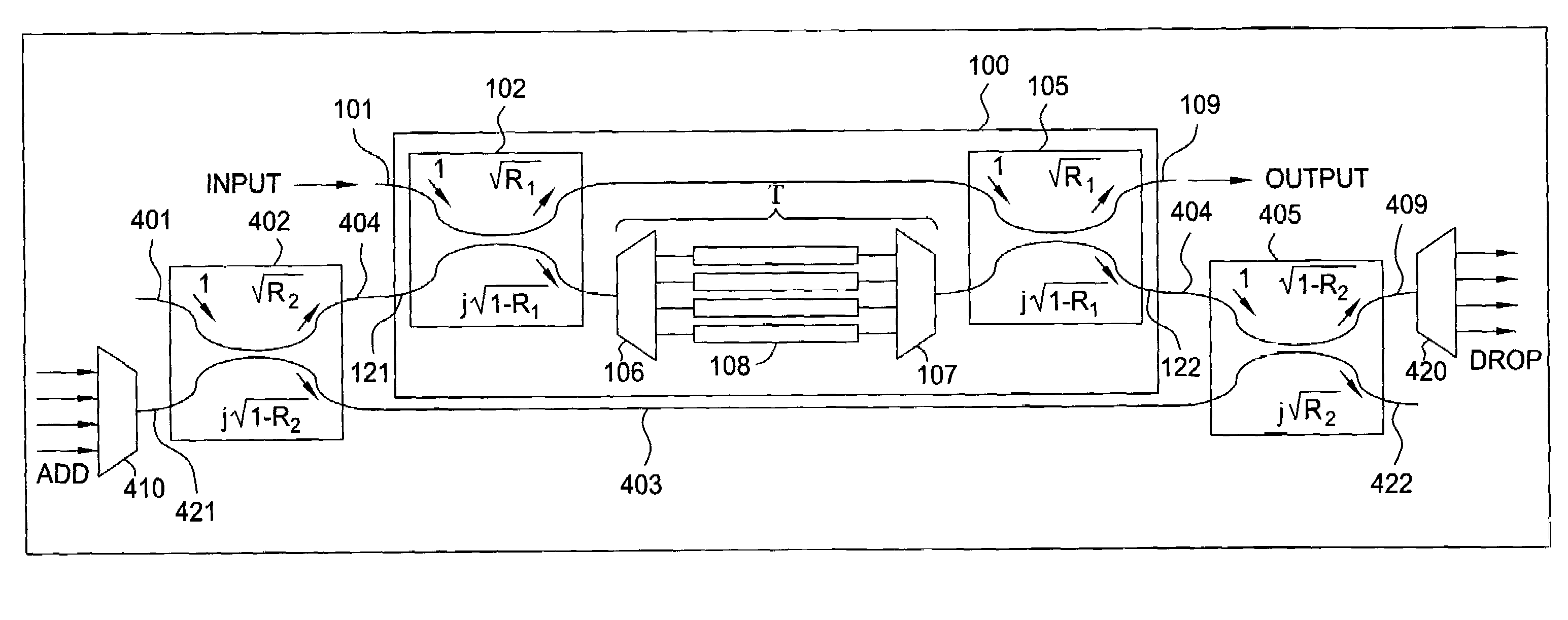
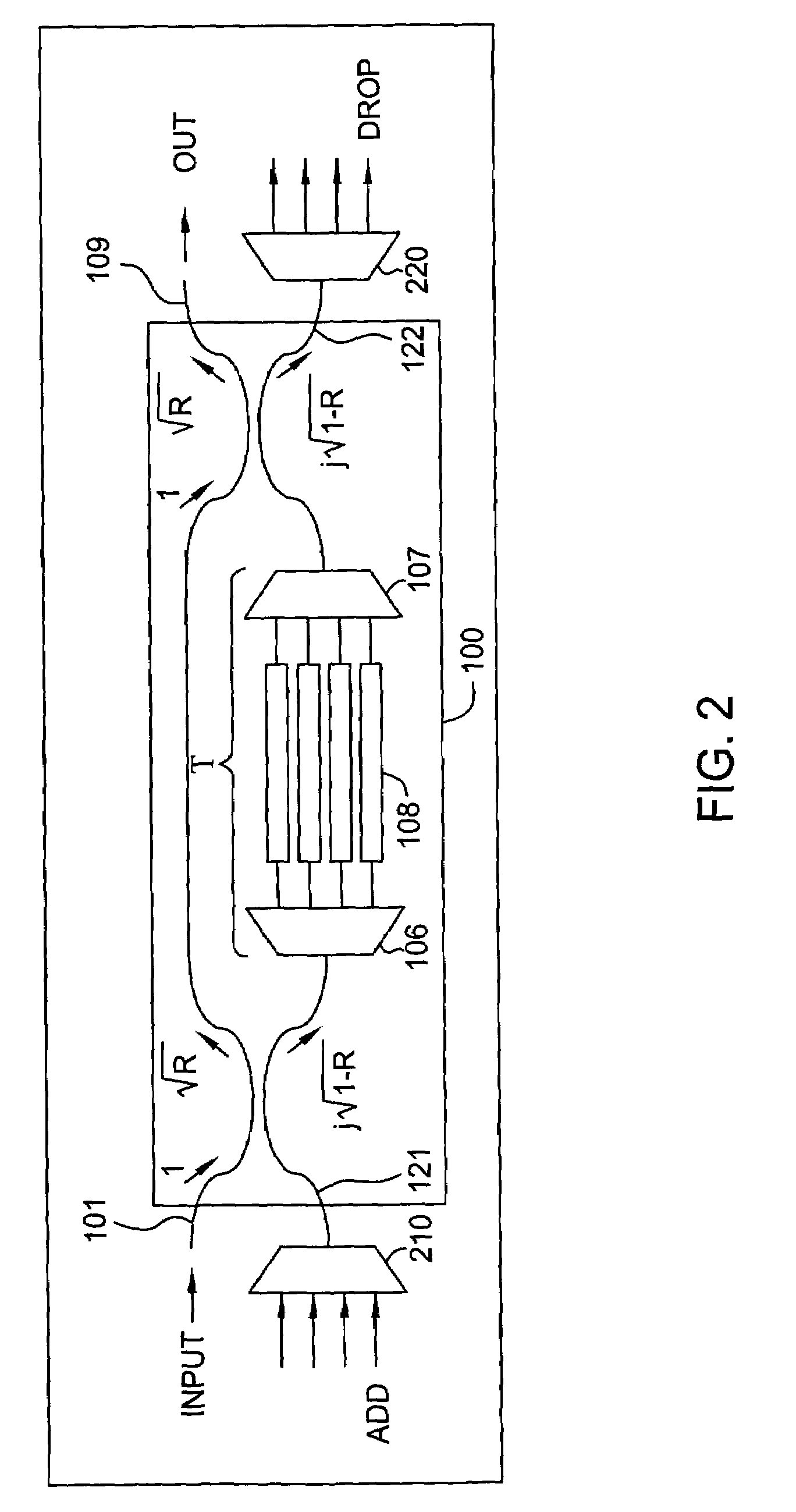
[0027]FIG. 2 depicts a block diagram of a reconfigurable optical add / drop multiplexer (ROADM). Specifically, the ROADM of FIG. 2 comprise an optical multiplexer 210, the DGEF 100, and a demultiplexer 220. The DGEF of 100 of FIG. 2 may be implemented in substantially the same manner as the DGEF 100 discussed with respect to FIG. 1.

[0028]The DGEF 100 in FIG. 1 has two unused ports 121 and 122. The ROADM of FIG. 2 connects the optical multiplexer 210 to the unused input port 121 of the DGEF 100. The unused output port 122 of the DGEF 100 is connected to the demultiplexer 220. A plurality of optical channels is multiplexed at multiplexer 210 and inputted to the DGEF 100. Depending ...


PUM


Abstract

A reconfigurable optical add / drop multiplexer (ROADM) includes a first optical dynamic gain equalization filter (DGEF) having a first input for receiving an initial wavelength division multiplexed (WDM) signal, a first output for sending a phase shifted WDM signal, and a second output connected to a demultiplexer for demultiplexing a WDM drop signal thereby producing a plurality of drop channels. A second DGEF having a first input for receiving the phase shifted WDM signal, a second input connected to a multiplexer, for multiplexing a plurality of add channels to produce thereby a wavelength division multiplexed (WDM) add signal, and an output for sending a second adjusted WDM signal. The ROADM allows for the channels from the initial WDM signal to be dropped, added and equalized.

Description

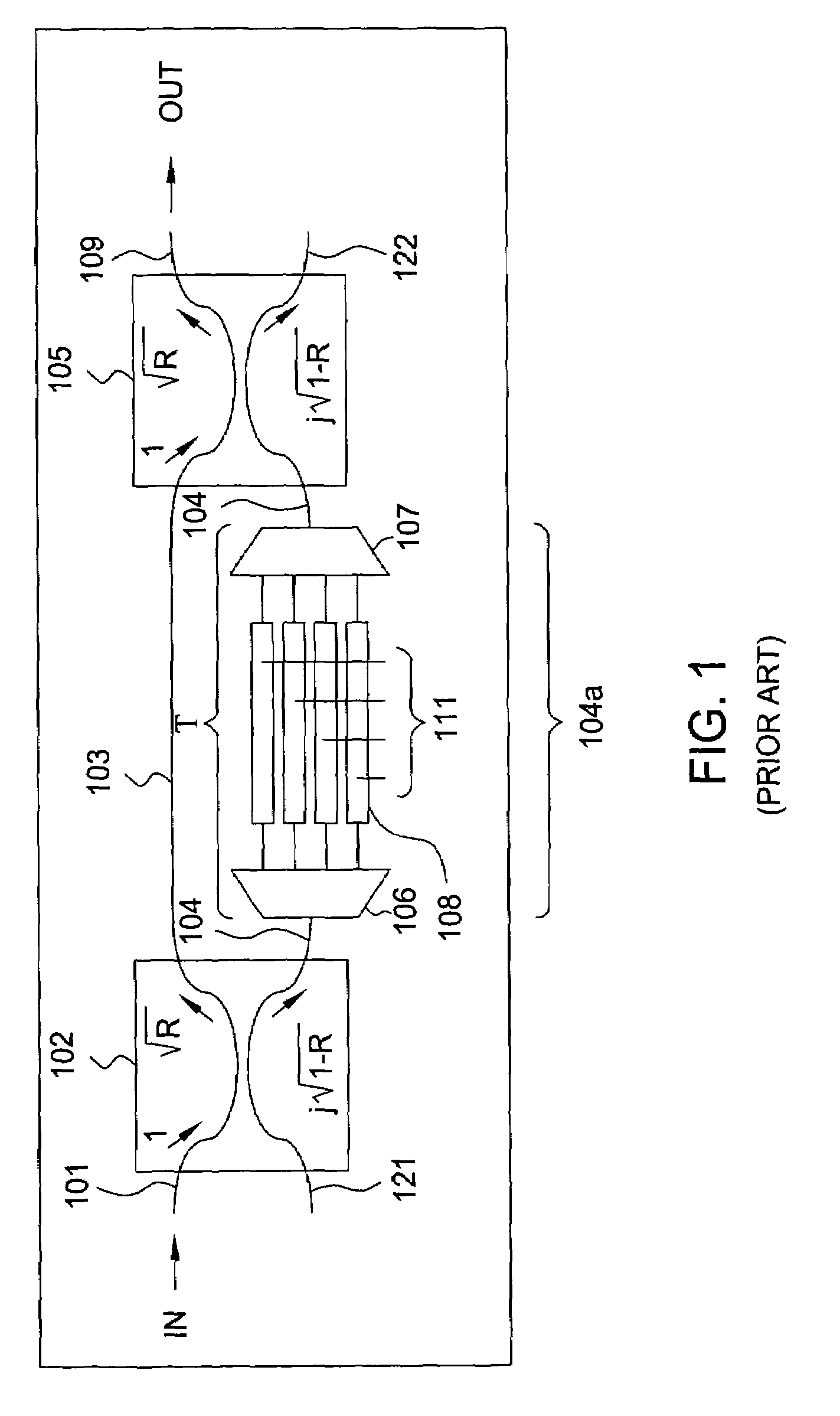
FIELD OF THE INVENTION[0001]The invention relates generally to optical communications and, more particularly, to an arrangement suitable for adding and dropping channels in a wavelength division multiplexed (WDM) optical system.BACKGROUND OF THE INVENTION[0002]A dynamic gain equalization filter (DGEF) is a device or arrangement that is useful for controlling optical WDM channel powers, especially at the dispersion compensating module (DCM) port of an in-line amplifier (ILA) to provide the desired spectral flatness of the output channels. An example of a DGEF is described in U.S. Pat. No. 6,212,315 by C. R. Doerr et al. titled “Channel Power Equalization for a Wavelength Divisioned Multiplexed system,” filed on Jul. 7, 1998, which is hereby incorporated by reference in its entirety.[0003]FIG. 1 depicts a block diagram of a DGEF 100 for controlling channel powers in wavelength-division multiplexed (WDM) systems. In the DGEF 100 of FIG. 1, a decrease in attenuation range can be traded ...

Claims


Application Information

Patent Timeline
Patent Type & Authority Patents(United States)
IPC IPC(8): G02B6/26
CPCG02B6/12007G02B6/2713G02B6/29383G02B6/29395G02B6/12021G02B6/2746G02B6/2766G02B6/2773
Inventor DOERR, CHRISTOPHER RICHARDJENNEN, JEAN GERARDUS LEONARDUS
Owner LUCENT TECH INC
Learn More