
SOI substrate for integration of opto-electronics with SiGe BiCMOS

a technology of opto-electronics and sos substrates, applied in the field of semiconductors, can solve the problems of requiring much thicker silicon, and reducing the feasibility of integrating optical components and bulk silicon electronics on a sos substra

Active Publication Date: 2008-03-04
NEWPORT FAB
View PDF11 Cites 17 Cited by
  • Summary
  • Abstract
  • Description
  • Claims
  • Application Information

AI Technical Summary

Benefits of technology

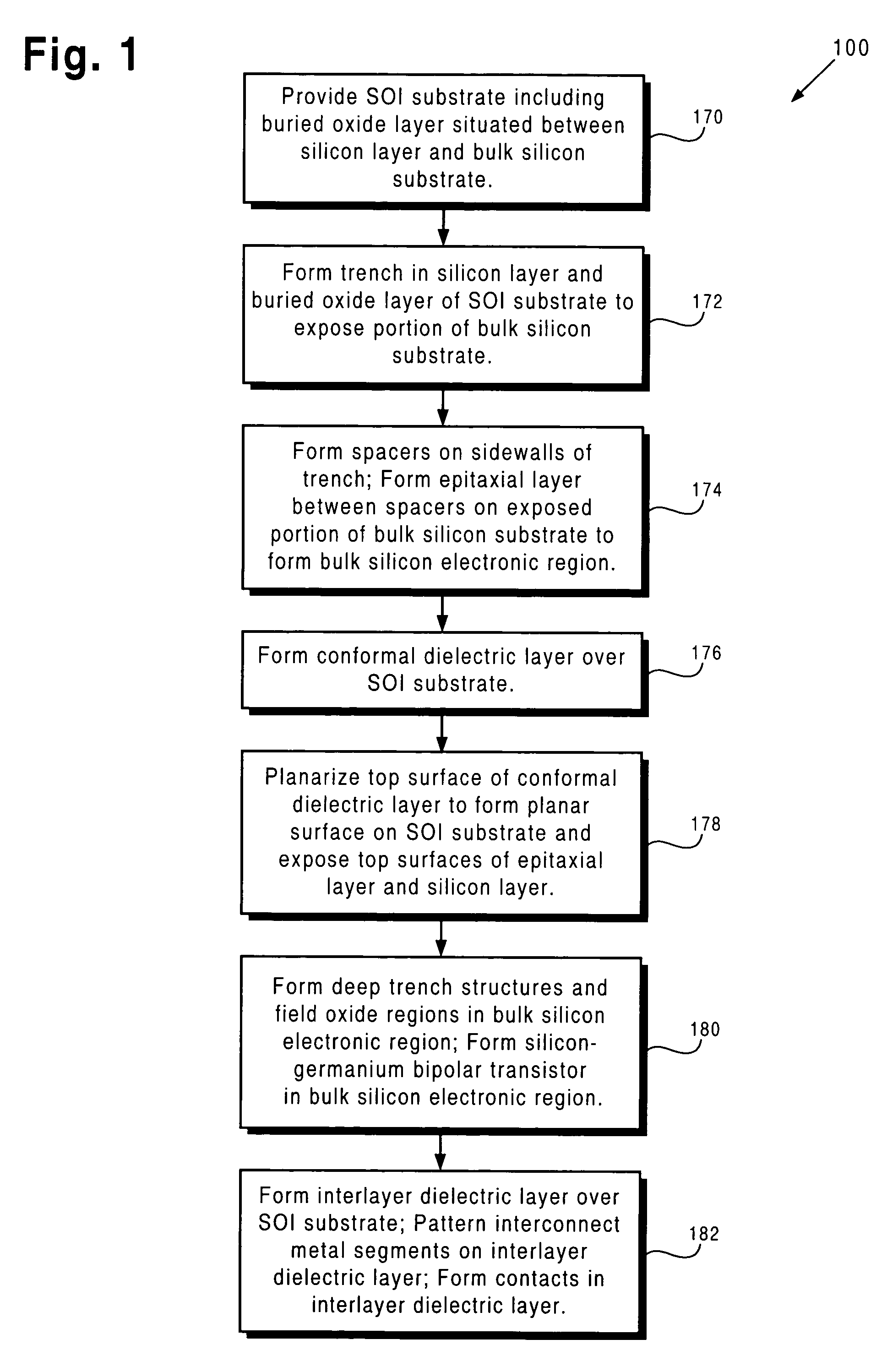
[0011]According to one embodiment, the invention is a method for fabricating the above-described structure. Other features and advantages of the present invention will become more readily apparent to those of ordinary skill in the art after reviewing the following detailed description and accompanying drawings.

Problems solved by technology

Different substrate requirements for optical components, such as waveguides, gratings, and modulators, and bulk silicon electronic devices, such as bulk silicon electronic devices formed using Bipolar Complementary-Metal-Oxide-Semiconductor (“BiCMOS”) technology, hinder the integration of optical components and bulk silicon electronics on a single substrate.
However, bulk silicon electronic devices, such as silicon-germanium (“SiGe”) bipolar transistors and other devices formed using SiGe BiCMOS technology, require much thicker silicon, such as silicon having a thickness of hundreds of microns.
However, an undesirably high defectivity rate in SOS substrates reduces the feasibility of integrating optical components and bulk silicon electronics on a SOS substrate.
Additionally, the cost of the SOS substrate is very high.

Method used


Image

  • SOI substrate for integration of opto-electronics with SiGe BiCMOS
  • SOI substrate for integration of opto-electronics with SiGe BiCMOS
  • SOI substrate for integration of opto-electronics with SiGe BiCMOS

Examples


Embodiment Construction

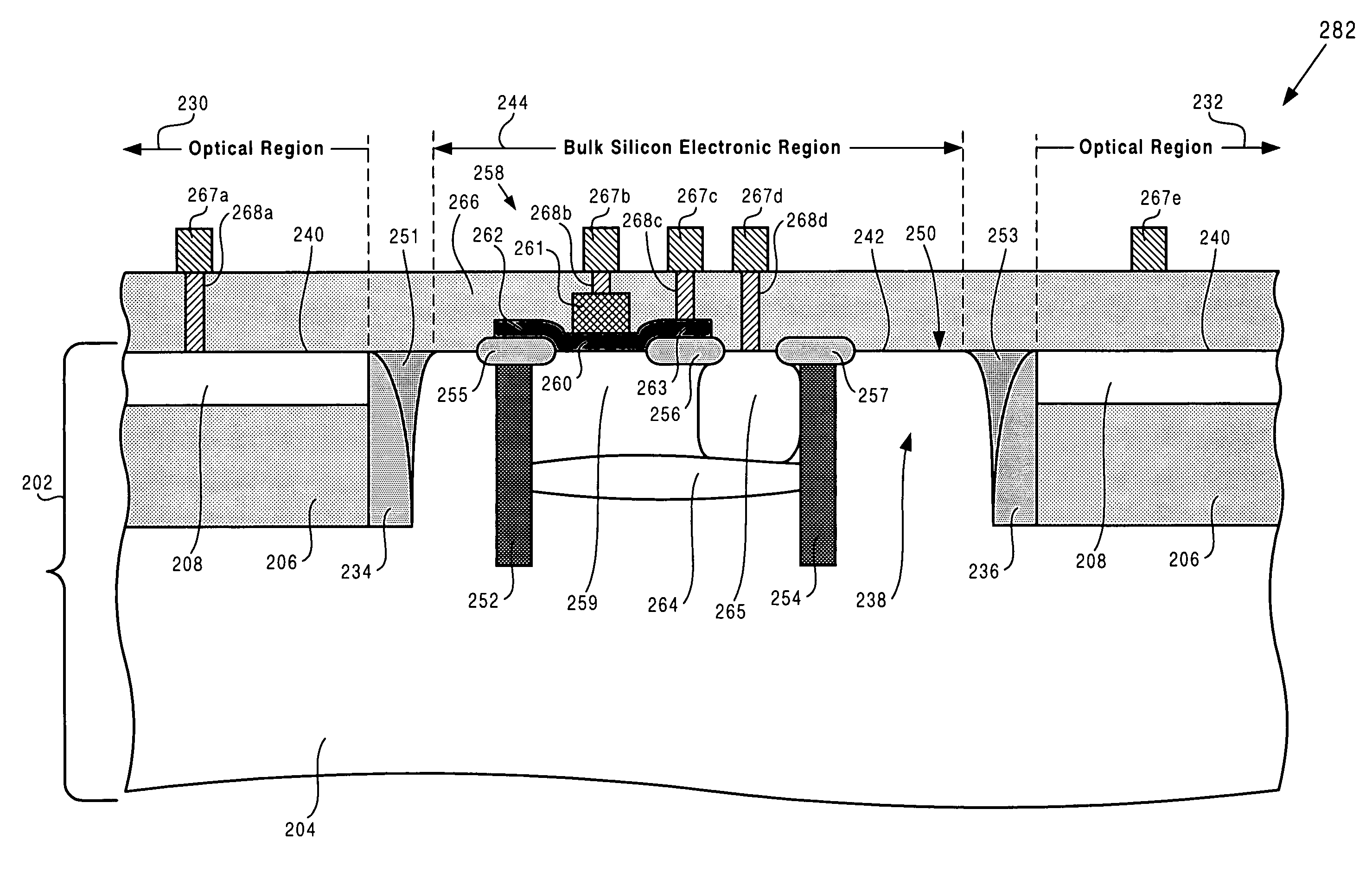
[0020]The present invention is directed to a SOI substrate for integration of opto-electronics with SiGe BiCMOS. The following description contains specific information pertaining to the implementation of the present invention. One skilled in the art will recognize that the present invention may be implemented in a manner different from that specifically discussed in the present application. Moreover, some of the specific details of the invention are not discussed in order to not obscure the invention. The specific details not described in the present application are within the knowledge of a person of ordinary skill in the art.

[0021]The drawings in the present application and their accompanying detailed description are directed to merely example embodiments of the invention. To maintain brevity, other embodiments of the invention which use the principles of the present invention are not specifically described in the present application and are not specifically illustrated by the pr...


PUM


Abstract

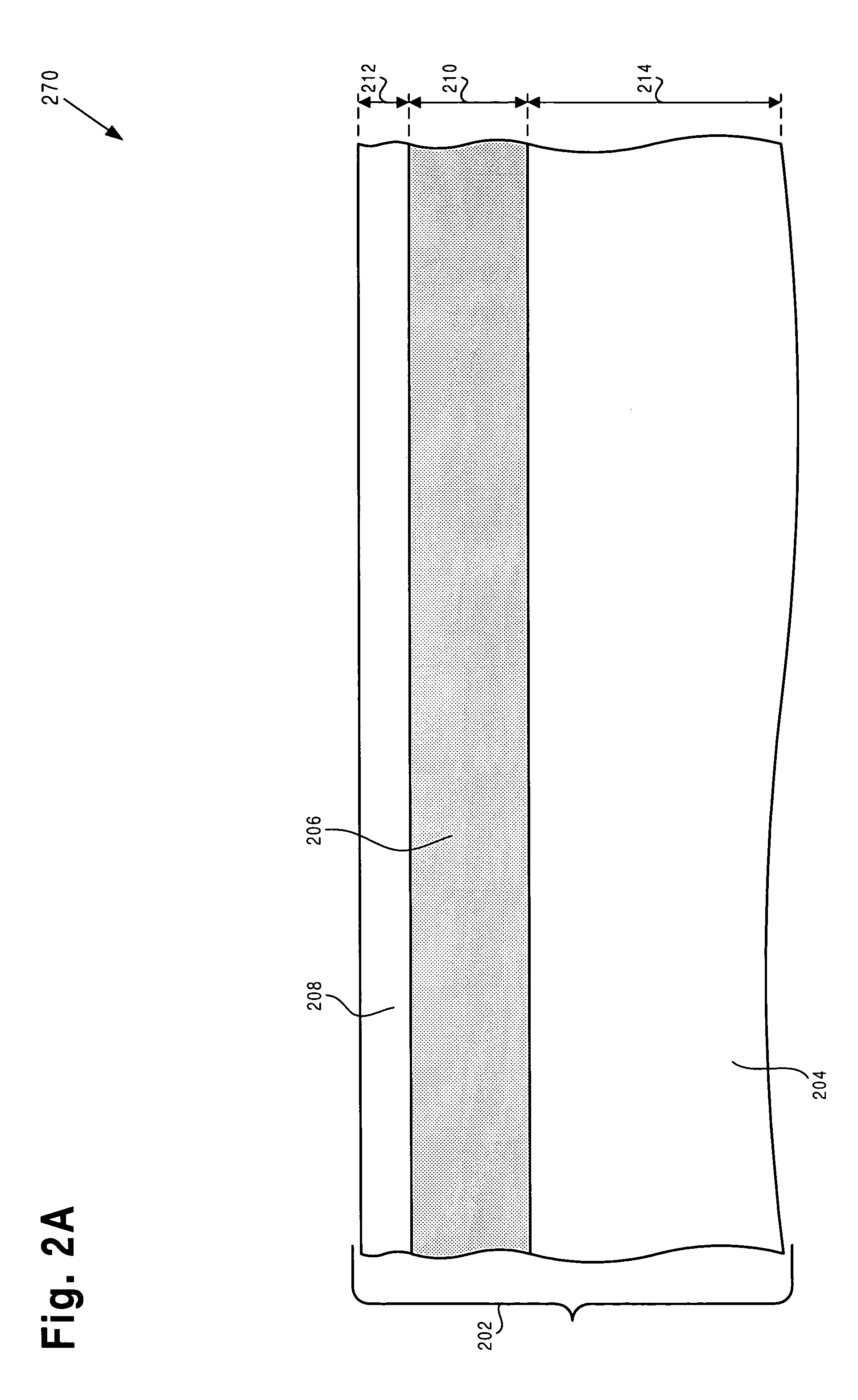
According to an exemplary embodiment, a structure includes a silicon-on-insulator substrate including a buried oxide layer situated over a bulk silicon substrate and a silicon layer situated over the buried oxide layer. The structure further includes a trench formed in the silicon layer and the buried oxide layer, where the trench has a bottom surface and a first and a second sidewall, and where the trench is situated adjacent to an optical region of the silicon-on-insulator substrate. According to this exemplary embodiment, the structure further includes an epitaxial layer situated in the trench and situated on the bulk silicon substrate, where the epitaxial layer and the bulk silicon substrate form a bulk silicon electronic region of the silicon-on-insulator substrate. The structure further includes a base of a bipolar transistor situated on the epitaxial layer, where the base can be silicon-germanium.

Description

[0001]The present application claims priority to, and is a continuation-in-part (“CIP”) of, a co-pending application entitled “Method for Opto-Electronic Integration on a SOI Substrate and Related Structure,” Ser. No. 10 / 970,645, filed on Oct. 20, 2004 and assigned to the assignee of the present invention. The disclosure in that co-pending application is hereby incorporated fully by reference into the present application.BACKGROUND OF THE INVENTION[0002]1. Field of the Invention[0003]The present invention is generally in the field of semiconductors. More specifically, the invention is in the field of semiconductor substrates for fabrication of optical components and bulk silicon electronics.[0004]2. Background Art[0005]Different substrate requirements for optical components, such as waveguides, gratings, and modulators, and bulk silicon electronic devices, such as bulk silicon electronic devices formed using Bipolar Complementary-Metal-Oxide-Semiconductor (“BiCMOS”) technology, hind...

Claims


Application Information

Patent Timeline
Patent Type & Authority Patents(United States)
IPC IPC(8): H01L27/082H01L27/102H01L29/70H01L31/11
CPCG02B6/136H01L21/76264H01L22/12G02B2006/12061H01L27/1203H01L27/1463H01L27/1207
Inventor KEMPF, PAUL H.
Owner NEWPORT FAB
Learn More