
Method of varying recording density of data storage medium and disk drive using the method

a technology which is applied in the field of changing the recording density of data storage medium and disk drive, can solve the problems of serious problems in using the system, data stored in regions adjacent to the specific region may be erased, and users cannot freely use the system, so as to reduce the recording density

Inactive Publication Date: 2008-02-26
SAMSUNG ELECTRONICS CO LTD
View PDF7 Cites 14 Cited by
  • Summary
  • Abstract
  • Description
  • Claims
  • Application Information

AI Technical Summary

Benefits of technology

[0009]An aspect of the present invention provides a method of varying a recording density of a data storage medium such that a user can designate a specific region of a recording medium and reduce a recording density of the specific region without changing a manufacturing process, and a disk drive using the method.
[0014]According to another aspect of the present invention, there is provided a method of writing data on a storage medium, including: reading region information including a start logic block address (LBA) and an end LBA of a region of the storage medium, a recording density of the region being changeable, when a write command including an LBA defining a write region is received; determining whether the received LBA is located between the start LBA and the end LBA; reducing the recording density of the write region by combining plural adjacent tracks in the write region into a data track, when the received LBA is located between the start LBA and the end LBA; and converting the changed LBA into a physical address and writing the data at a target track of the storage medium corresponding to the physical address.

Problems solved by technology

In this case, when data is written on the specific region, the specific region is excessively magnetized, and thus data stored in regions adjacent to the specific region may be erased.
If data in an important region such as the FAT are erased, it can cause serious problems in using the systems.
However, the conventional method still has a problem in that since the recording density of the disk is fixed in a manufacturing process, a user cannot freely designate a specific region according to use and cannot reduce a recording density of the specific region.

Method used


Image

  • Method of varying recording density of data storage medium and disk drive using the method
  • Method of varying recording density of data storage medium and disk drive using the method
  • Method of varying recording density of data storage medium and disk drive using the method

Examples


Embodiment Construction

[0022]Reference will now be made in detail to embodiments of the present invention, examples of which are illustrated in the accompanying drawings, wherein like reference numerals refer to the like elements throughout. The embodiments are described below in order to explain the present invention by referring to the figures.

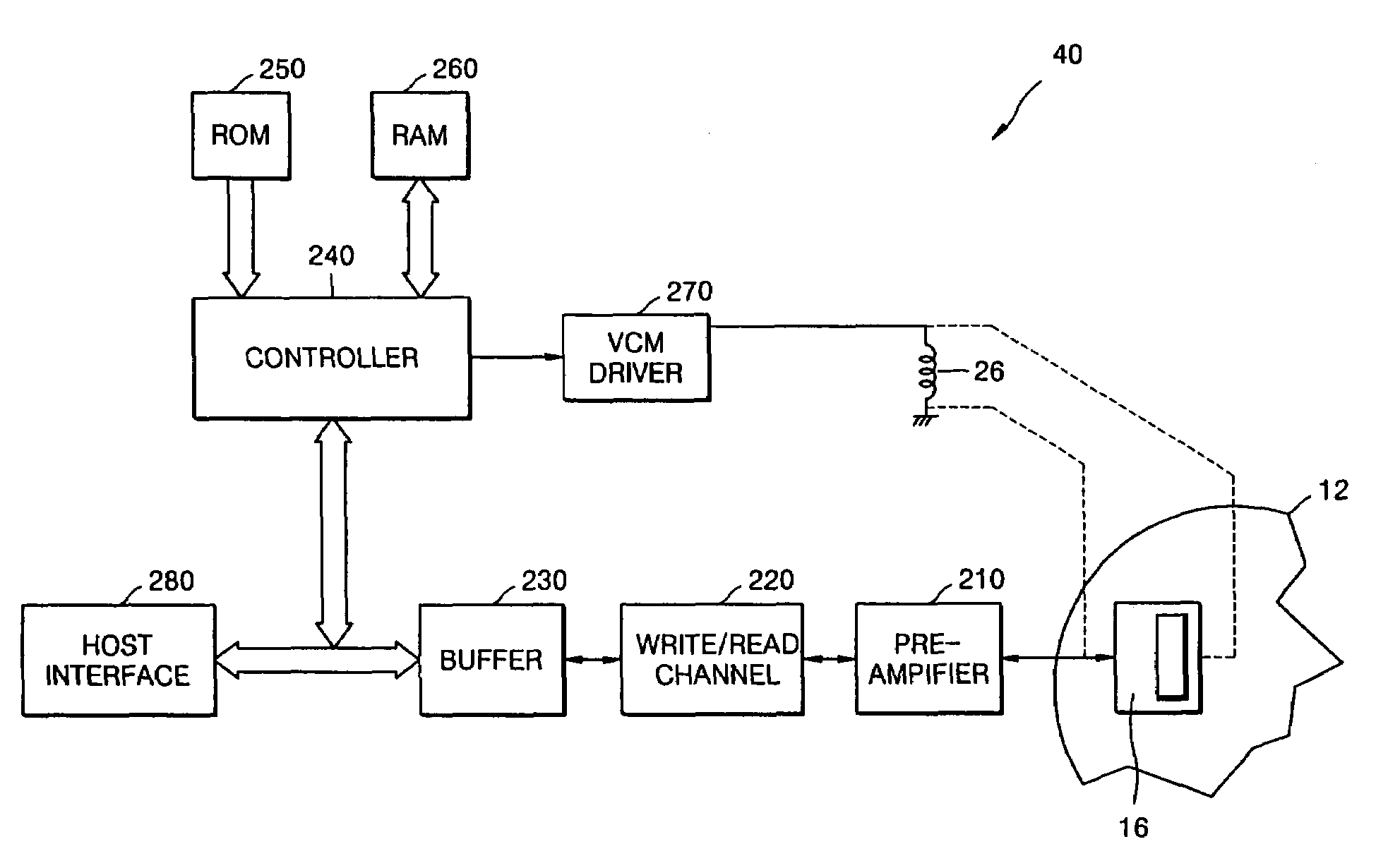
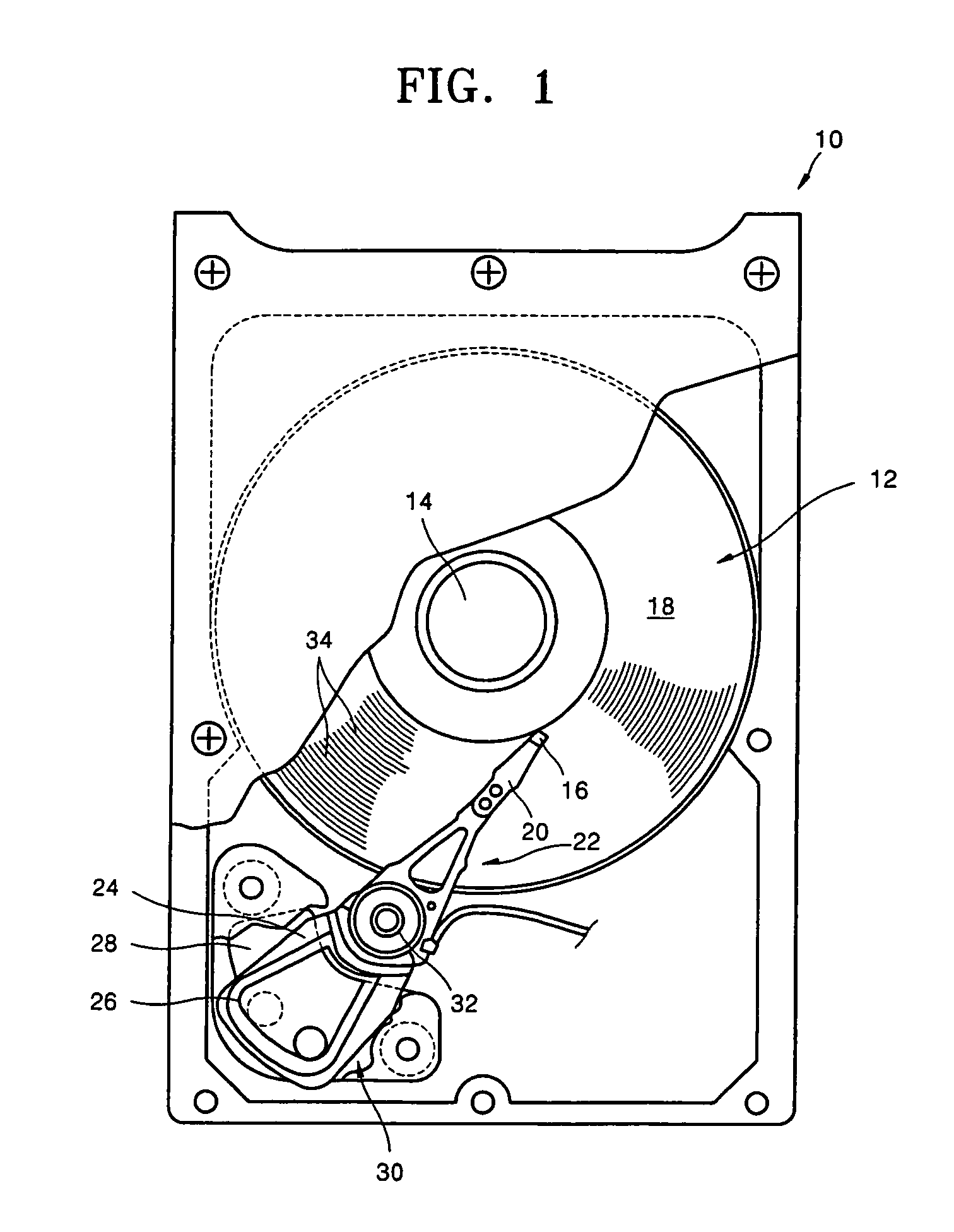
[0023]FIG. 1 is a top view of a hard disk drive (HDD) 10 to which an embodiment of the present invention is applied. The HDD 10 includes at least one magnetic disk 12 that is rotated by a spindle motor 14. The disk drive 10 further includes a transducer 16 located adjacent to a disk surface 18.

[0024]The transducer 16 can read or write information on each rotating disk 12 by detecting a magnetic field of the disk 12 and magnetizing the disk 12. The transducer 16 is generally associated with the disk surface 18. Although the transducer 16 is shown as one body, it is to be understood that the transducer 16 includes of a write transducer for magnetizing the disk 12 an...


PUM


Abstract

A method of and apparatus for varying a recording density of a data storage system. The method includes setting a range of a region whose recording density is to be changed, judging whether a region in which data read and write commands are to be executed is within the set range, and performing data read and write operations by allocating only one data among a plurality of continuous tracks as a data track if the region in which the data read and write commands are to be executed is within the set range.

Description

CROSS-REFERENCE TO RELATED APPLICATION[0001]This application claims the priority of Korean Patent Application No. 2004-0090782, filed on Nov. 9, 2004, in the Korean Intellectual Property Office, the disclosure of which is incorporated herein in its entirety by reference.BACKGROUND OF THE INVENTION[0002]1. Field of the Invention[0003]The present invention relates to a method of and apparatus for changing a recording density of a data storage system, and more particularly, to a method of varying a recording density of a data storage medium such that a user can easily change a recording density of a recording medium without changing a manufacturing process, and a disk drive using the method.[0004]2. Description of Related Art[0005]In general, hard disk drives (HDDs), which are data storage devices, contribute to the operation of a computer system by reading data written on a disk or writing data on the disk using a magnetic head. In line with a recent trend toward high capacity, high d...

Claims


Application Information

Patent Timeline
Patent Type & Authority Patents(United States)
IPC IPC(8): G06F13/00
CPCG11B5/02G11B20/1217G11B27/034G11B27/105G11B2220/2516
Inventor CHO, SUNG-YOUNJEONG, SEUNG-YOULPARK, JONG-LAK
Owner SAMSUNG ELECTRONICS CO LTD
Learn More