
Method and unit for suppressing a periodic pattern

a technology of periodic patterns and suppression methods, applied in image enhancement, image analysis, instruments, etc., can solve problems such as image sharpness reduction

Inactive Publication Date: 2008-02-26
FUJIFILM HLDG CORP +1
View PDF17 Cites 28 Cited by
  • Summary
  • Abstract
  • Description
  • Claims
  • Application Information

AI Technical Summary

Benefits of technology

[0008]The present invention has been made in view of the aforementioned circumstances. Accordingly, it is the primary object to provide a periodic-pattern suppression method and a periodic-pattern suppression unit which are capable of making a periodic pattern (such as a stripe pattern, which develops in an image because of a stationary grid, etc., and the like) inconspicuous without reducing sharpness.

Problems solved by technology

Thus, there is a problem that an image will be reduced in sharpness.

Method used


Image

  • Method and unit for suppressing a periodic pattern
  • Method and unit for suppressing a periodic pattern
  • Method and unit for suppressing a periodic pattern

Examples


Embodiment Construction

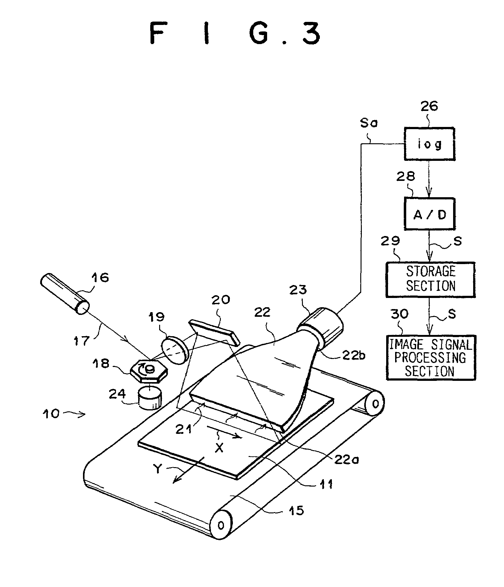
[0068]A preferred embodiment of the present invention will hereinafter be described in detail with reference to the drawings. The following description will be made according to a mode, in which in a radiation image information recording-reproducing system utilizing a storage-type fluorescent sheet as a recording sheet, the radiation image of a human body recorded on the recording sheet is read out as a digital image signal by laser-beam scanning, as described in the aforementioned Japanese Unexamined Patent Publication Nos. 55(1980)-12429, 56(1981)-11395, etc.

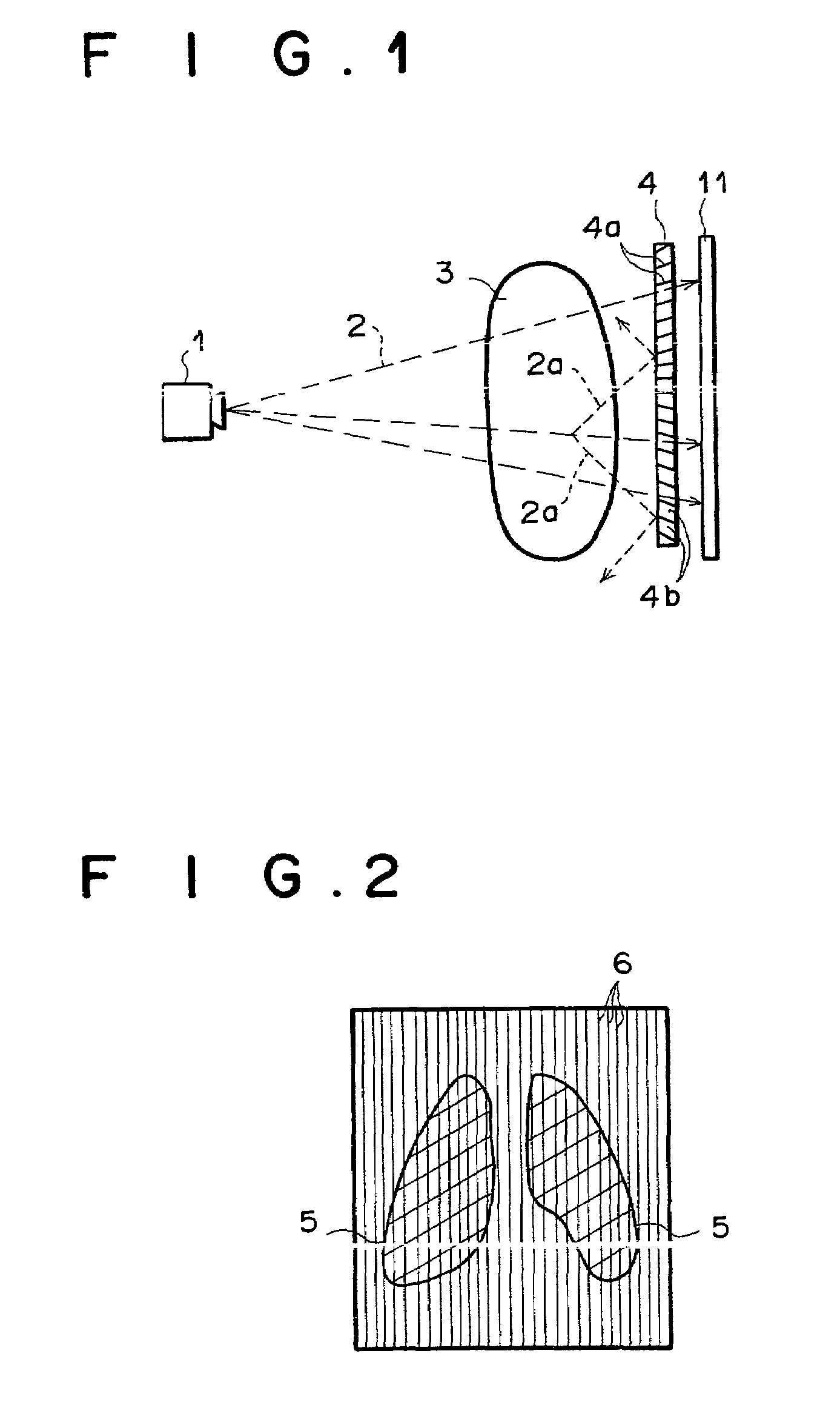
[0069]FIG. 1 schematically shows a radiation image photographing apparatus. As shown in the figure, radiation 2 emitted from a radiation source 1 passes through a subject 3 and reaches a grid 4. In the grid 4, lead plates 4a which absorb the radiation 2 and aluminum plates 4b which transmit the radiation 2 are alternately disposed at pitches of 4 plate / mm with a slight tilt in accordance with position so that the radiation 2 e...


PUM


Abstract

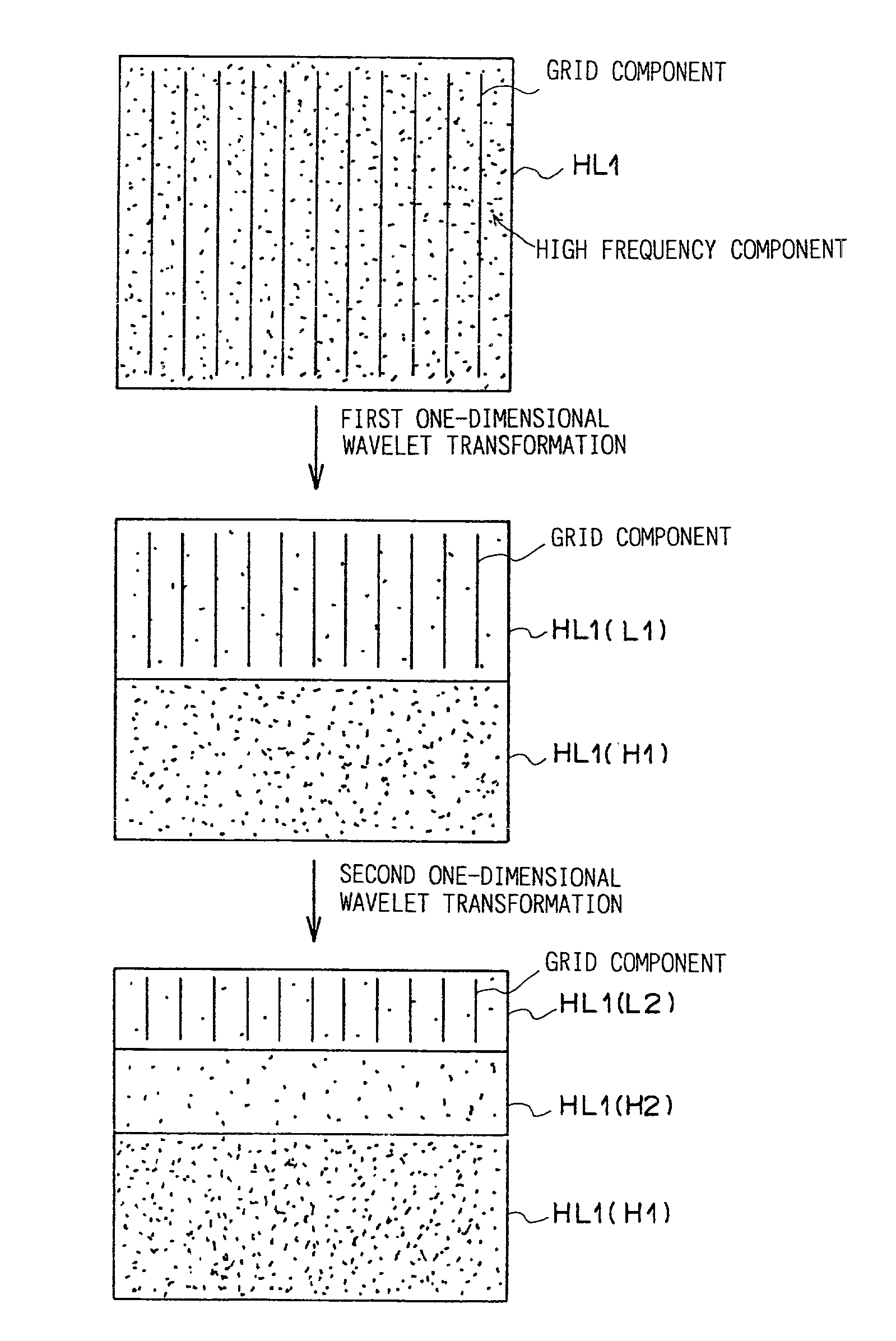
In a wavelet transform section, wavelet-transform coefficient signals are obtained by two-dimensional wavelet transformation, employing a low-pass filter which has a characteristic that its response at a frequency greater than a spatial frequency corresponding to grid pitch is approximately zero. Based on the direction of the grid judged by a direction judging section, a suppressing section applies one-dimensional wavelet transformation to a signal containing a grid component (when a vertical grid is used, signal HL1), in the grid direction. Then, a low frequency transform coefficient signal of the transform coefficient signals is made zero. The signal, made zero, and the remaining signals, are subjected to inverse one-dimensional wavelet transformation. In an inverse wavelet transform section, the original image is restored with a signal having a suppressed grid component.

Description

BACKGROUND OF THE INVENTION[0001]1. Field of the Invention[0002]The present invention relates to a periodic-pattern suppression method and unit, and more particularly to a method and unit for reducing and removing a stripe pattern (including a moire component), corresponding to a stationary grid, from an image photographed, for example, by use of the stationary grid, the image having the stripe pattern superposed on the image of a subject.[0003]2. Description of the Related Art[0004]Radiation recording-reproducing systems have been proposed in Japanese Unexamined Patent Publication Nos. 55(1980)-12429, 56(1981)-11395, 55(1980)-163472, 56(1981)-164645, 55(1980)-116340, etc. These systems utilize a storage-type phosphor (stimulatable phosphor), which stores part of radiation energy when irradiated with radiation, such as X-rays, etc., and emits photostimulated luminescent light according to the amount of the stored radiation energy when irradiated with excitation light such as visible...

Claims


Application Information

Patent Timeline
IPC IPC(8): G06K9/00G06K9/36G06T5/10
CPCG06T5/10G06T5/002G06T2207/20064A61B6/5252G06T5/70
Inventor TAKEO, HIDEYA
Owner FUJIFILM HLDG CORP
Learn More