Method and apparatus for steady state analysis of a voltage controlled oscillator

a steady state analysis and voltage control technology, applied in the field of computer-aided steady state analysis of electronic circuits, can solve the problems of non-conventional technique of determining the control voltage of a vco, difficult to verify whether the circuit is real, and inconvenient to perform, etc., to achieve short run-time, efficient computation, and accurate manner

Active Publication Date: 2008-02-19
SIEMENS PROD LIFECYCLE MANAGEMENT SOFTWARE INC
View PDF4 Cites 5 Cited by
  • Summary
  • Abstract
  • Description
  • Claims
  • Application Information

AI Technical Summary

Benefits of technology

[0016]The steady state analysis of a VCO according to the present invention has the advantage that the steady state and the control voltage that result in a given frequency or period of oscillation can be efficiently computed. Unlike conventional steady state analysis of VCOs that cannot calculate the control voltage directly, the present invention provides a way of computing the control voltage and steady state directly with short run-time and in an accurate manner.

Problems solved by technology

For example, a well-known but error-prone conventional technique of determining the period of oscillation of a VCO is to run a dynamic transient simulation of the VCO circuit.
The period of oscillation can be estimated by measuring the difference in times when the output signal waveform of the VCO crosses a predetermined constant value for two consecutive times. However, this conventional technique is error prone, because it is difficult to verify whether the circuit has indeed reached a steady state for all the nodes in the VCO circuit.
So far, there has been non conventional technique of determining the control voltage of a VCO given a known period or frequency of oscillation of the VCO.
However, this iterative technique is very inefficient, since it requires multiple, iteratively steady state computations of the VCO circuit to determine the correct control voltage.

Method used


Image

  • Method and apparatus for steady state analysis of a voltage controlled oscillator
  • Method and apparatus for steady state analysis of a voltage controlled oscillator
  • Method and apparatus for steady state analysis of a voltage controlled oscillator

Examples


Embodiment Construction

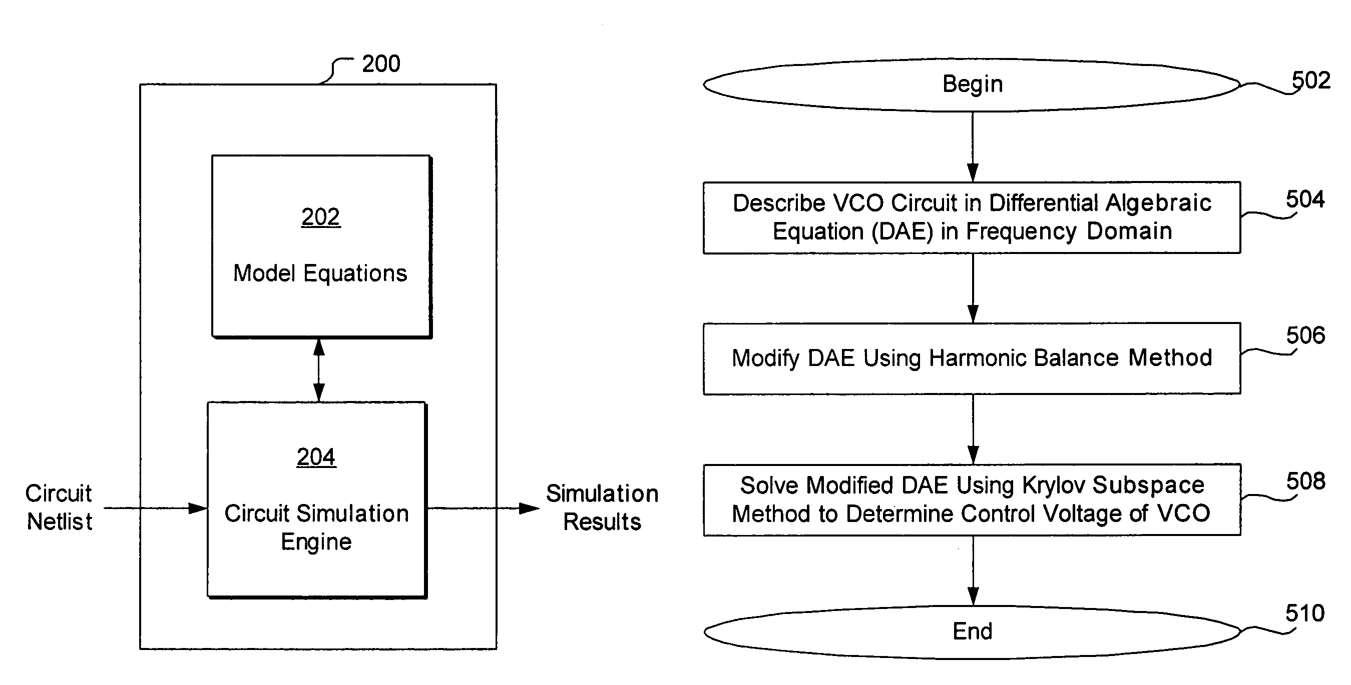
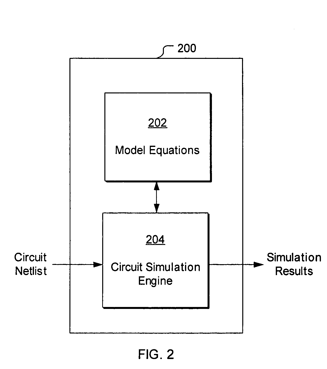
[0024]FIG. 2 is a block diagram illustrating a circuit simulation system 200, according to one embodiment of the invention. The circuit simulation system 200 includes a circuit simulation engine 204 and a database 202 of model equations coupled to the circuit simulation engine. The circuit simulation system 200 is typically circuit simulation software running on a computer. The model equations database 202 includes analytical models modeling the behavior of a variety of circuit components (e.g., capacitor, inductors, transistors, diodes, etc.) that are typically included in electronic circuits, for use in generating DAEs representing the circuit to be simulated. The circuit simulation engine 204 is configured to receive a circuit netlist describing the nodes and connections of the electronic circuit to be simulated, generate DAEs representing the circuit based on the netlist and the model equations, and execute a variety of algorithms. for solving the DAEs. For example, the circuit ...


PUM


Abstract

A computer-implemented method computes the steady-state and control voltage of a voltage controlled oscillator, given a known frequency or a known period of oscillation of the voltage controlled oscillator. Differential algebraic equations representative of the voltage controlled oscillator are generated, where the differential algebraic equations includes a known period or frequency of oscillation and an unknown control voltage of the voltage controlled oscillator. The differential algebraic equations are modified using a finite difference method, a shooting method, or a harmonic balance method, to obtain a set of matrix equations corresponding to the differential algebraic equations. A solution to the matrix equations is obtained using a Krylov subspace method, using a preconditioner for the Krylov subspace method that is derived from a Jacobian matrix corresponding to the matrix equations, where the solution includes the control voltage of the voltage controlled oscillator in steady state.

Description

TECHNICAL FIELD[0001]The present invention relates to computer-aided analysis of electronic circuits and, more specifically, to computer-aided steady state analysis of voltage controlled oscillators.BACKGROUND OF THE INVENTION[0002]An oscillator is a widely used electronic circuit component that generates a periodic output voltage signal at a particular frequency. An oscillator is an autonomous circuit in the sense that the oscillator can generate a periodic output voltage signal by applying only constant bias signals to the oscillator, through a self-sustaining mechanism that causes repeated amplification of the oscillator's own noise that eventually becomes a large periodic voltage signal. When the amplitude of the oscillation reaches a predetermined level, another different mechanism of the oscillator limits further growth of the signal so that the amplitude of the oscillation maintains the predetermined level. The amplitude and frequency of the oscillation is usually determined ...

Claims


Application Information

Patent Timeline
IPC IPC(8): G06F17/50G01R23/06
CPCG06F17/5036G06F17/504G06F30/3323G06F30/367
Inventor MEHROTRA, AMITNARAYAN, AMIT
Owner SIEMENS PROD LIFECYCLE MANAGEMENT SOFTWARE INC
Why Eureka
Try Eureka