
Fabrication of narrow-band thin-film optical filters

a thin-film optical filter and fabrication technology, applied in the field of optical filters, can solve the problem of reducing the degree of structural non-uniformities propagated, and achieve the effect of reducing the spectral bandwidth

Inactive Publication Date: 2008-02-19
MEADE INSTRUMENTS
View PDF4 Cites 15 Cited by
  • Summary
  • Abstract
  • Description
  • Claims
  • Application Information

AI Technical Summary

Benefits of technology

[0014]This invention provides a new approach to the manufacture of multi-layer thin-film filters which allows the fabrication of filters with significantly reduced spectral bandwidth and permits post-fabrication tuning, if necessary, to the exact spectral-position specification of the filter's band. The invention is based on the exploitation of two distinct ideas in the process of multi-layer filter manufacture.
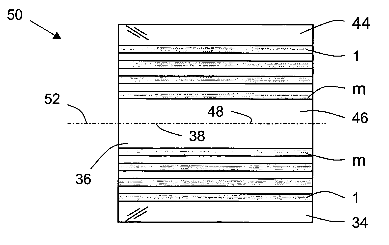
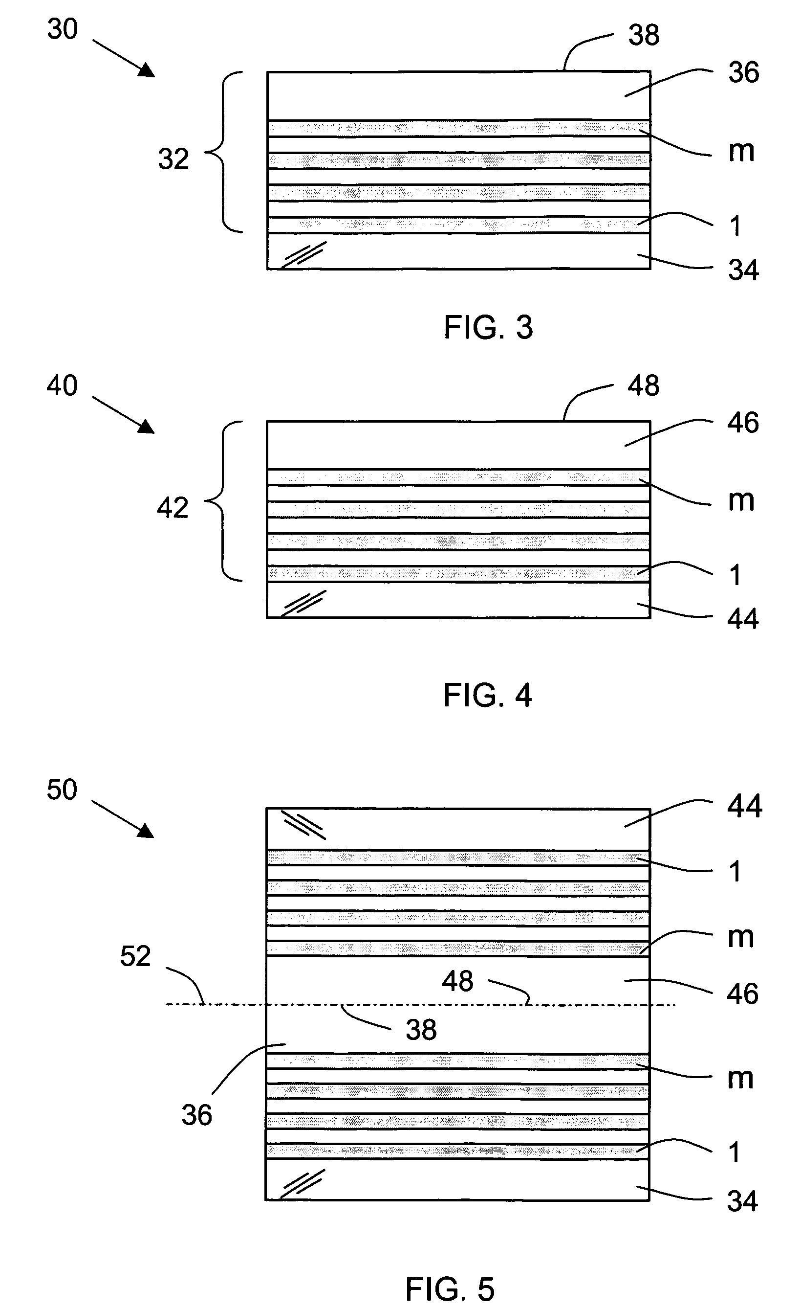
[0015]According to one aspect of the invention, the fabrication sequence is carried out in a way that reduces the number of thin-film layers that are grown consecutively on top of one another in a filter stack. This approach significantly reduces the degree of structural non-uniformities propagated within the layers of the stack during the film deposition process and maximizes the structural symmetry of the filter. This is achieved by employing the process in which each half of the symmetric stack is deposited under exact conditions, either successively or contemporaneously.

Problems solved by technology

This approach significantly reduces the degree of structural non-uniformities propagated within the layers of the stack during the film deposition process and maximizes the structural symmetry of the filter.

Method used


Image

  • Fabrication of narrow-band thin-film optical filters
  • Fabrication of narrow-band thin-film optical filters
  • Fabrication of narrow-band thin-film optical filters

Examples


Embodiment Construction

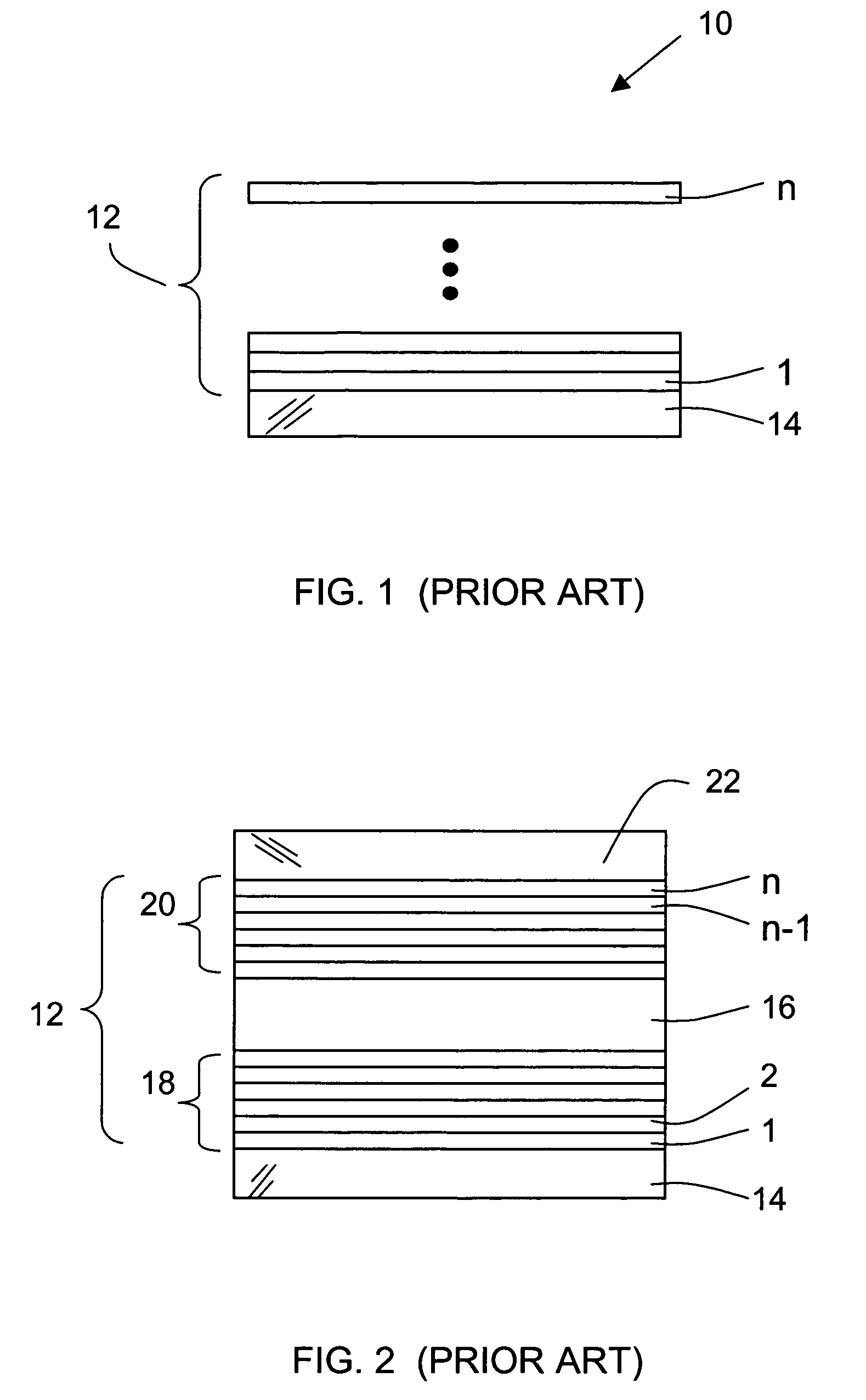
[0030]The heart of the invention lies in the idea of substituting the conventional sequence of fabrication of symmetric thin-film filters (which always progresses sequentially by depositing each layer on top of the previous one, starting with the first layer in the stack and ending with its last layer) with a process wherein only each half of the symmetric stack is deposited sequentially. The two half stacks are then combined to produce the symmetric full-stack structure of the filter.

[0031]Narrow-band filters fabricated with this two-step approach produce significant advantages over analogous filters manufactured by conventional methods. First, they exhibit a substantially narrower width in the stop (or pass) band of interest, which is critically important in many applications. Second, the filter can be adjusted after fabrication to correct the exact spectral position of the filter's stop (or pass) band, if necessary, which is not possible with conventional filters.

[0032]According ...


PUM

PropertyMeasurementUnit
rms roughnessaaaaaaaaaa
refractive indexaaaaaaaaaa
roughnessaaaaaaaaaa

Abstract

A multi-layer thin-film narrow-band filter is fabricated by a process wherein each half of a symmetric stack is deposited under exact conditions, either successively or contemporaneously. The two halves of the filter structure are then combined and bonded together using a wet bonding process that remains reversible for a period of time sufficient for testing the filter and, if necessary, for separating the two halves to regain access to the spacer layer. Accordingly, the spacer layer may be adjusted to shift the peak wavelength, if necessary, to the precise design specifications for a particular application. After correction, the components of the symmetric filter are bonded again using the same wet process.

Description

RELATED APPLICATIONS[0001]This application is based on and claims the priority of U.S. Provisional Application Ser. No. 60 / 544,447, filed Feb. 13, 2004.BACKGROUND OF THE INVENTION[0002]1. Field of the Invention[0003]This invention relates to the general field of optical filters and, in particular, to the manufacture of multi-layered thin-film optical structures.[0004]2. Description of the Prior Art[0005]Optical filters are widely used as components of optical systems. In particular, they are employed in various spectroscopic and optical communication systems where information is transmitted within very narrow spectral bands. In order to retrieve the information contained in a particular band, the remaining spectral background (or spectral noise) has to be filtered out. This is achieved generally using optical filters that pass or reject (stop) the input light within a predetermined narrow-band spectral range.[0006]A wide variety of optical filters is known in the art, the most funda...

Claims


Application Information

Patent Timeline
Patent Type & Authority Patents(United States)
IPC IPC(8): B32B37/00B32B38/04G02B5/28
CPCB32B37/24G02B5/282G02B5/288B32B38/164B32B2037/243Y10T156/1075B32B2551/00
Inventor SIDORIN, YAKOVHOGAN, LEGAL REPRESENTATIVE, GERALDINELUNT, DAVID L.
Owner MEADE INSTRUMENTS
Learn More