
Ink-jet printer and method of controlling ink-jet printer

a technology of inkjet printer and ink cartridge, which is applied in the field of inkjet printer and the control of inkjet printer, can solve the problems of reducing the ink-ejecting performance of the ink-jet recording head, large amount of ink consumed uselessly, etc., and achieves accurate results. , the effect of effectively preventing useless ink consumption

Active Publication Date: 2008-02-12
BROTHER KOGYO KK
View PDF6 Cites 1 Cited by
  • Summary
  • Abstract
  • Description
  • Claims
  • Application Information

AI Technical Summary

Benefits of technology

The present invention provides an ink-jet printer and method for controlling it that can accurately determine the amount of air present in the ink supply and ink inflow passages and effectively discharge the air without consuming unnecessary ink. This is achieved by controlling the air supplying device and air-discharge valve based on the elapsed time and volume of air present at the time of air discharge. The invention ensures a high ink-ejecting performance of the printer and prevents wasted ink consumption during air discharging operations.

Problems solved by technology

If the air discharging operation is so performed as to discharge completely the air present in the ink-supply tube even if the total amount of the air may be large, then a large amount of the ink must be discharged together with the air, i.e., the large amount of ink is consumed uselessly.
On the other hand, if the air discharging operation is so performed as to discharge only a small amount of the ink, then only an insufficient amount of the air may be discharged, which may lead to lowering the ink-ejecting performance of the ink-jet recording head.

Method used


Image

  • Ink-jet printer and method of controlling ink-jet printer
  • Ink-jet printer and method of controlling ink-jet printer
  • Ink-jet printer and method of controlling ink-jet printer

Examples


first embodiment

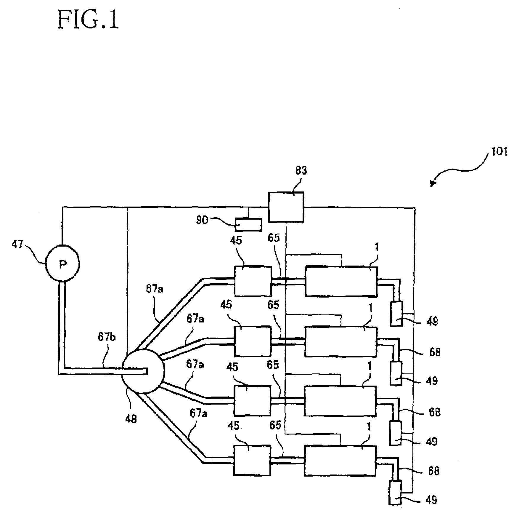
[0039]FIG. 1 schematically shows a construction of an ink-jet printer 101 as a first embodiment of the present invention. The ink-jet printer 101 is for recording a desired image on a recording medium, e.g., a recording sheet, by ejecting droplets of ink onto the sheet. As shown in FIG. 1, the ink-jet printer 101 includes four ink-jet recording heads 1; four ink tanks 45 corresponding to the four ink-jet heads 1, respectively; an air pump 47; a switching unit (i.e., an air valve) 48; an air-discharge valve 49; and a control device 83.

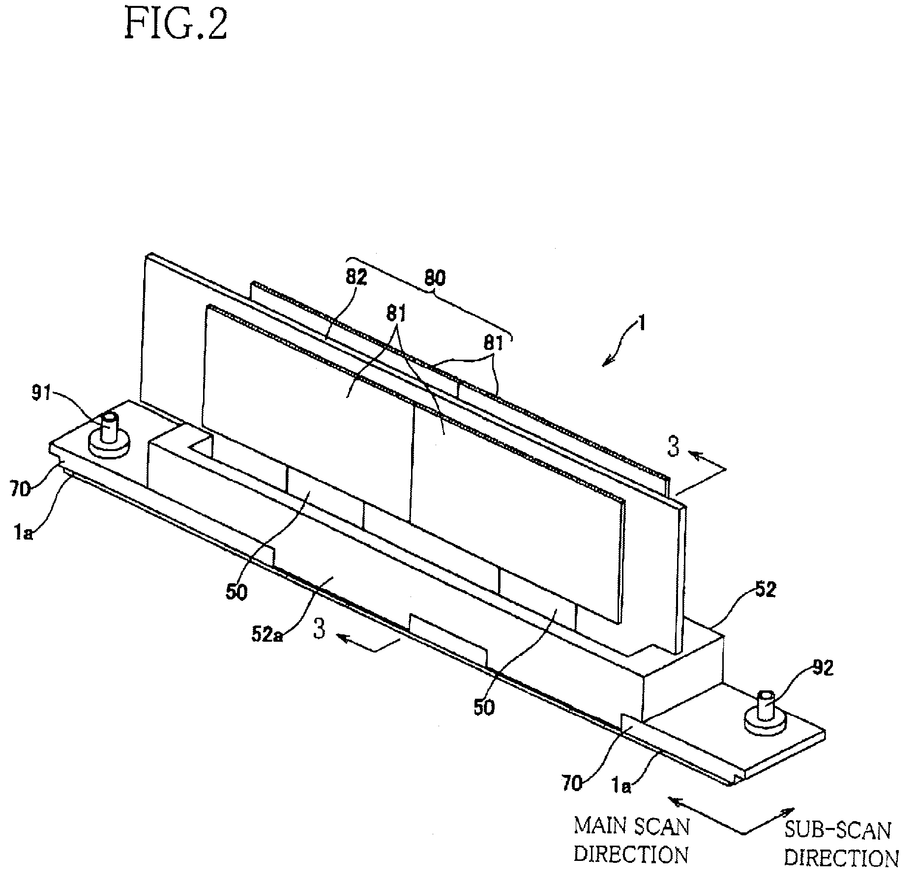
[0040]Each ink-jet recording head 1 is a serial-type recording head that ejects droplets of ink onto the recording sheet while being moved in a main scan direction perpendicular to a sub-scan direction in which the recording sheet is fed by a feeding device, not shown. The four ink-jet heads 1 are configured such that the four heads 1 eject droplets of four different inks, respectively. The four different inks are a cyan ink, a yellow ink, a magenta ink...

second embodiment

[0095]Next, a second embodiment of the present invention will be described by reference to FIGS. 15 and 16. The second embodiment relates to an ink-jet printer having the same hardware construction as that of the ink-jet printer 101 shown in FIGS. 1 through 9 and 10A through 10H. The ink-jet printer as the second embodiment differs from the ink-jet printer 101 as the first embodiment, with respect to only the functions of a control device 283. The same reference numerals as used in the first embodiment shown in FIGS. 1 through 9, 10A through 10H, and 11 are used to designate the corresponding elements or parts of the second embodiment, and the description thereof is omitted. FIG. 15 shows the functions of the control device 283 of the ink-jet printer as the second embodiment. The control device 283 controls the ink-jet printer as a whole, e.g., the ink-jet recording heads 1, the air pump 47, the switching unit 48, and the air-discharge valves 49. As shown in FIG. 15, the control dev...

third embodiment

[0109]Next, a third embodiment of the present invention will be described by reference to FIG. 17. The third embodiment relates to an ink-jet printer 301, shown in FIG. 17, for ejecting droplets of inks toward a recording medium and thereby forming desired images on the same. The same reference numerals as used in the first embodiment shown in FIGS. 1 through 9, 10A through 10H, and 11 are used to designate the corresponding elements or parts of the third embodiment, and the description thereof is omitted. As shown in FIG. 17, the ink-jet printer 301 includes the four ink-jet recording heads 1, the four ink tanks 45 corresponding to the four ink-jet recording heads 1; an air tank 46; the air pump 47; the switching unit (i.e., air valve) 48; the four air-discharge valves 49; the temperature humidity sensor 90; an atmosphere-communication air valve 349; and a control device 383.

[0110]The air tank 46 has an air supply port 46a, an air outlet 46b, and an atmosphere-communication port 46...


PUM


Abstract

An ink-jet printer, including an ink-jet recording head having an ink inflow passage including an ink inlet, and an air-discharge passage which allows the ink inflow passage to communicate with an atmosphere; an air-discharge valve which selectively opens and closes the air-discharge passage; an ink tank which stores the ink and which has an ink outlet and an air inlet; a connector having an ink supply passage which communicates, at one end thereof, with the ink outlet of the ink tank and communicates, at an other end thereof, with the ink inlet of the recording head; an air supplying device which supplies the air to the ink tank via the air inlet thereof; an obtaining portion which obtains one of an elapsed time, t, from a reference time, and a volume, V, of an air present in the ink supply passage and the ink inflow passage at the elapsed time t, based on an other of the elapsed time t and the air volume V, and a following relationship: V=a·ebt, where a and b are coefficients and e is a base of a natural logarithm; and a control portion which controls, based on the obtained one of the elapsed time t and the air volume V, an operation of the air supplying device and / or the air-discharge valve, so that the volume V of the air at the elapsed time t is discharged through the air-discharge passage opened by the air-discharge valve.

Description

[0001]The present application is based on Japanese Patent Application No. 2005-150535 filed on May 24, 2005, the contents of which are incorporated herein by reference.BACKGROUND OF THE INVENTION[0002]1. Field of the Invention[0003]The present invention relates to an ink-jet printer that ejects droplets of ink onto a recording medium, and a method of controlling an ink-jet printer.[0004]2. Discussion of Related Art[0005]There is known an ink-jet printer including an ink-jet recording head that ejects droplets of ink; an ink tank that stores an ink to be supplied to the recording head via a flexible ink-supply tube; and an air tank that stores air to be supplied to the ink tank. An example of this ink-jet printer is disclosed by Japanese Patent Application Publication No. 2004-58348 or its corresponding U.S. Patent Application Publication No. 2004 / 0196326A1. This ink-jet printer has such a problem that air enters the flexible ink-supply tube through its wall and, as time elapses, air...

Claims


Application Information

Patent Timeline
Patent Type & Authority Patents(United States)
IPC IPC(8): B41J2/125
CPCB41J2/175B41J2/17513B41J2/17556B41J2/17566
Inventor KAGA, HIKARU
Owner BROTHER KOGYO KK
Learn More