
System and method of direct mesh manipulation

a mesh model and system technology, applied in the field of computer-assisted vehicle design, can solve the problems of time-consuming and costly process of using a cad system to update a mesh model, and the modification of a cad model in a cad system is a very time-consuming and labor-intensive task

Active Publication Date: 2008-01-29
FORD GLOBAL TECH LLC
View PDF9 Cites 44 Cited by
  • Summary
  • Abstract
  • Description
  • Claims
  • Application Information

AI Technical Summary

Benefits of technology

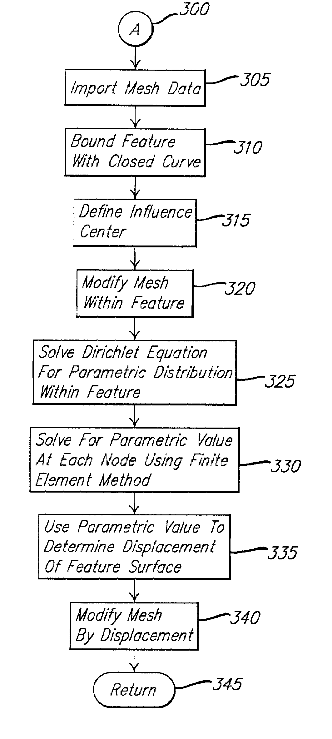
The present invention is a system and method for computer-aided engineering analysis using direct mesh manipulation of a mesh model. This technology allows for verification of design intent and prediction of mechanical behavior of a model early in the design process. It also replaces physical experiment on a physical prototype with a computer aided engineering simulation using a computer model. The design parameter can be expeditously modified and analyzed. The technology uses aDirichlet parameter distribution to determine deformation of the surface feature, models the surface as a linear elastic sheet, and uses finite element analysis to solve for deformation of the surface. The technology also uses lattice deformation techniques to deform the surface feature. Overall, this technology provides a more efficient and accurate means of design analysis and optimization.

Problems solved by technology

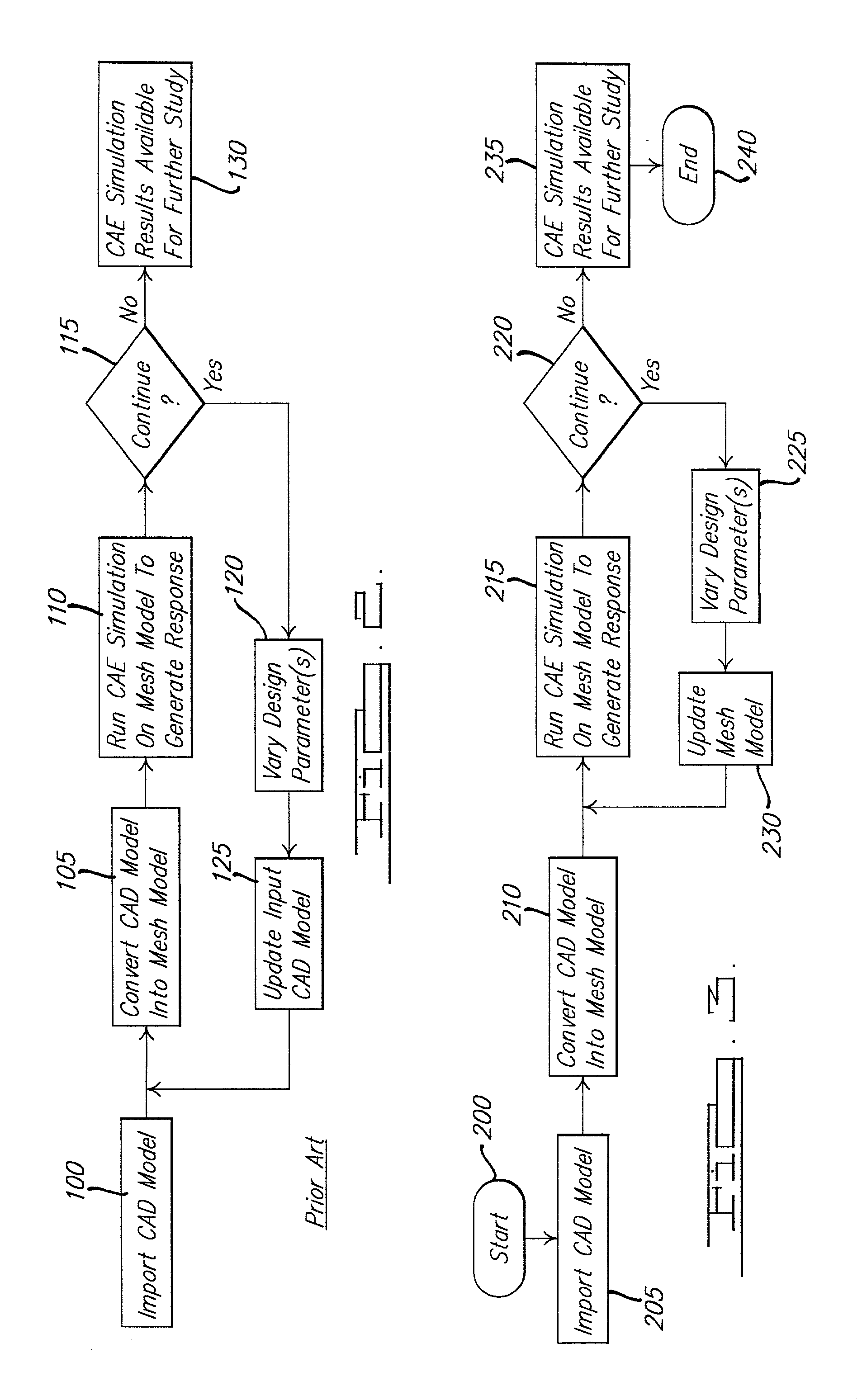
However, modifying the CAD model in a CAD system is a very time-consuming task that is performed each time a change is made to the system parameter set.
Also, the use of a CAD system in updating a mesh model is a time consuming and costly process, since CAD systems generally require significant overhead, including user background, experience and training.

Method used


Image

  • System and method of direct mesh manipulation
  • System and method of direct mesh manipulation
  • System and method of direct mesh manipulation

Examples


Embodiment Construction

)

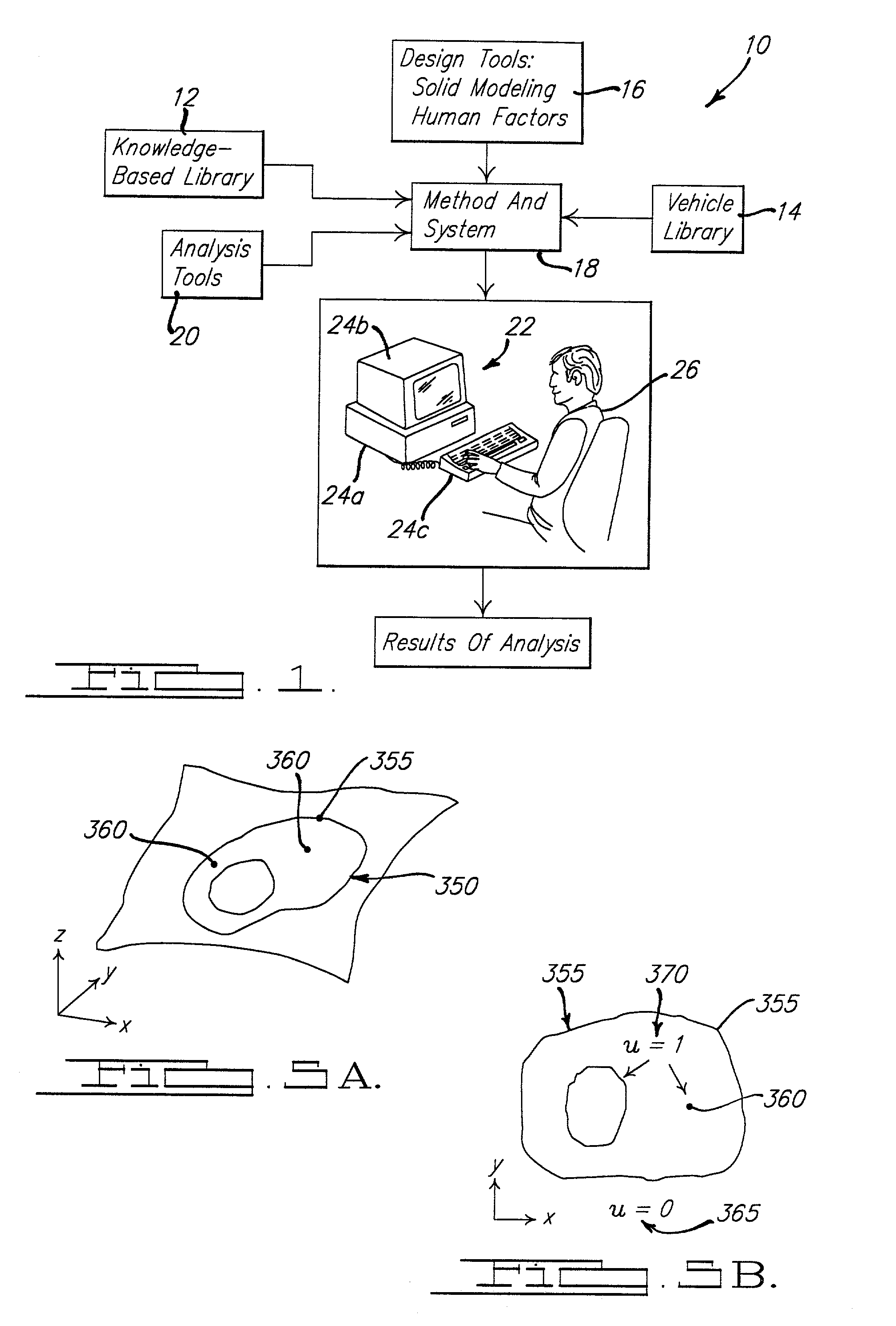
[0019]A design of a system, such as a vehicle, is achieved according to the present invention with a generic, parametric driven design process. Advantageously, this process allows for flexibility in vehicle design and engineering analysis of the design in a fraction of the time required using conventional design methods. Various computer-based tools are integrated to achieve this enormous time and expense savings, including solid modeling, parametric design, and automated studies.

[0020]In this example, the computer generated geometric model represents a design form for a vehicle, partially shown at 50. The vehicle design is typically generated through the use of conventional computer aided design (CAD), including computer aided manufacturing (CAM) and computer aided engineering (CAE) techniques.

[0021]Referring to the drawings and in particular to FIG. 1, a system 10 for direct mesh manipulation of a mesh model, which in this example is a vehicle 50, is illustrated graphically. The ...


PUM


Abstract

A system and method for computer-aided engineering analysis using direct mesh manipulation of a mesh model is provided. The system includes a computer system having a memory, a processor, a user input device and a display device. The method includes the steps of selecting a geometric model in a computer-aided design (CAD) format, converting the CAD model into a mesh model and evaluating the mesh model using a computer-aided engineering (CAE) analysis. The method also includes the steps of modifying a surface of the mesh model by varying a predetermined parameter using direct surface manipulation (DSM), updating the mesh model and using the updated mesh model in further CAE analysis. Three techniques are provided for modifying a surface feature, including using a Dirichlet parameter distribution to determine the displacement of the surface feature; modeling the surface feature as an elastic sheet to determine deformation; and enclosing the feature within a lattice structure and using lattice deformation to determine surface deformation.

Description

BACKGROUND OF THE INVENTION[0001]1. Field of the Invention[0002]The present invention relates generally to computer-assisted design of vehicles and, more specifically, to a system and method of direct manipulation of a mesh model in the computer-assisted design of a vehicle.[0003]2. Description of the Related Art[0004]Vehicle design, and in particular the design of an automotive vehicle, has advanced to a state in which computer-assisted design techniques are frequently incorporated in the development of a new vehicle, or redesign of an existing vehicle. At the same time, enhanced visualization software tools have been developed that allow for interactive display and manipulation of large geometric models, including models developed using computer-aided design (CAD), such as a vehicle model. In the field of vehicle design, the combined use of computer-aided design and visualization techniques are especially beneficial in designing, packaging and assembling the various systems incorp...

Claims


Application Information

Patent Timeline
Patent Type & Authority Patents(United States)
IPC IPC(8): G06T17/00G06F17/50G06T17/20
CPCG06F17/5018G06F17/5095G06T17/20G06F2217/42Y10S715/964G06F2113/24G06F30/23G06F30/15
Inventor STEWART, PAUL JOSEPHMARSAN, ANNECHEN, YIFAN
Owner FORD GLOBAL TECH LLC
Learn More