
Interrogation system for active monitoring of structural conditions

a technology of active monitoring and diagnostic system, applied in the direction of instruments, force/torque/work measurement, apparatus for force/torque/work measurement, etc., can solve the problems of time-consuming and expensive, inability to control the sensory device, and increased complexity of the network device network

Inactive Publication Date: 2008-01-29
ADVANCED STRUCTURE MONITORING
View PDF37 Cites 24 Cited by
  • Summary
  • Abstract
  • Description
  • Claims
  • Application Information

AI Technical Summary

Benefits of technology

"The patent describes a system for monitoring the health of structures using patch sensors attached to the structure. The system includes a relay unit with switches that establish channels between the sensors and a root node, allowing for the transmission of signals. The system also includes a programmable memory unit, a data acquisition control signal, and a wave generation control signal to select the appropriate sensor. The system can store and transmit data wirelessly to a remote receiver. The technical effect of this system is to provide a reliable and efficient way to monitor the health of structures in real-time, allowing for early detection and timely maintenance."

Problems solved by technology

Although still used for inspection of isolated locations, they are time-consuming and expensive.
As the number of sensory devices in the host structure has increased, the complexity in networking the devices has also increased, and, as a consequence, the conventional network topology, such as matrix or multiplexer, may not be suitable for controlling the sensory devices.
In some cases, inadequate network topology may limit the operational speed of the diagnostic systems.

Method used


Image

  • Interrogation system for active monitoring of structural conditions
  • Interrogation system for active monitoring of structural conditions
  • Interrogation system for active monitoring of structural conditions

Examples


embodiment 180

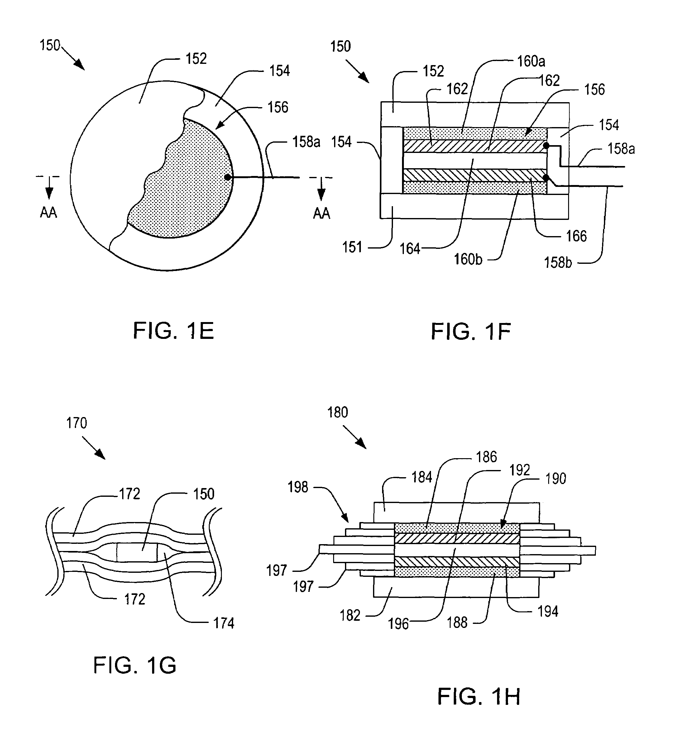
[0067]FIG. 1H is a schematic side cross-sectional view of an alternative embodiment 180 of the patch sensor 150 of FIG. 1E. As illustrated, the patch sensor 180 may include: a bottom substrate 182; a top substrate 184; a hoop layer 198; a piezoelectric device 190; top and bottom buffer layers 192 and 194; and the piezoelectric device 196. For simplicity, a pair of wires connected to the piezoelectric device 190 is not shown in FIG. 1H. The piezoelectric device 190 may include: a piezoelectric layer 196; a bottom conductive flake 194; and a top conductive flake 192. The functions and materials for the components of the patch sensor 180 may be similar to those of their counterparts of the patch sensor 150.

[0068]The hoop layer 198 may have one or more sublayers 197 of different dimensions so that the outer contour of the hoop layer 198 may match the geometry of cavity 174. By filling the cavity 174 with sublayers 197, the adhesive material may not be accumulated during the curing proce...

embodiment 318

[0080]FIG. 3C a schematic top cut-away view of the optical fiber coil 308 contained in the optical fiber patch sensor of FIG. 3A, illustrating a method for rolling the optical fiber cable 312. As shown in FIG. 3C, the outermost loop of the optical fiber coil 308 may start with one end 310a while the innermost loop may end with the other end 310b. FIG. 3D a schematic top cut-away view of an alternative embodiment 318 of the optical fiber coil 308 shown in FIG. 3C. As shown in FIG. 3D, the optical fiber cable 322 may be folded and rolled in such a manner that the outermost loops may start with both ends 320a-b. The rolled optical fiber cable 322 may be covered by a coating layer 319.

[0081]It is noted that the optical fiber coils 308 and 318 show in FIGS. 3C-D may be attached directly to a host structure and used as optical fiber coil sensors. For this reason, hereinafter, the terms “optical fiber coil” and “optical fiber coil sensor” will be used interchangeably. FIGS. 3E-F are altern...


PUM

PropertyMeasurementUnit
temperatureaaaaaaaaaa
thicknessaaaaaaaaaa
loop diameteraaaaaaaaaa

Abstract

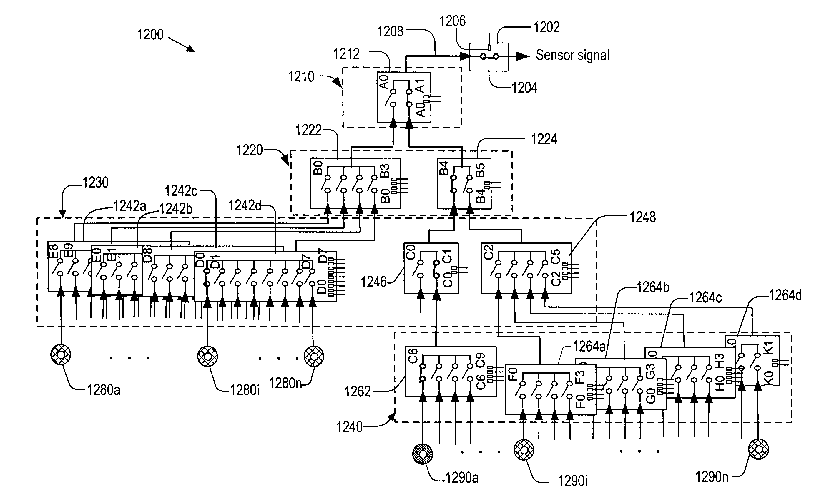
Systems for monitoring structural health conditions of objects. Each system includes patch sensors attached to an object, wherein each patch sensor is capable of generating a wave upon receipt of an actuator signal and developing a sensor signal in response to the wave. The system includes a tree structured relay unit that has a root node and at least one lower level node that includes at least one leaf node connected to the patch sensors. The lower level node includes switches, wherein the switches are operated to establish a channel between the root node and a selected one of the patch sensors and wherein actuator signal or sensor signal is transmitted through the channel. The sensor signals are analyzed to monitor health conditions thereby prevent catastrophic failure.

Description

CROSS REFERENCE TO RELATED APPLICTIONS[0001]This application is a continuation-in-part of application Ser. No. 10 / 942,366, filed on Sep. 16, 2004, now U.S. Pat. No. 7,117,742, which claims the benefit of U.S. Provisional Applications No. 60 / 505,120, filed on Sep. 22, 2003.BACKGROUND[0002]The present invention relates to diagnostics of structures, and more particularly to diagnostic network patch (DNP) systems for monitoring structural health conditions.[0003]In general, structures in service may require periodic inspections and appropriate maintenance services to prolong their life and / or to prevent catastrophic failures. Numerous methods have been employed to identify fault or damage of structures, where these methods may include conventional visual inspection and non-destructive techniques, such as ultrasonic and eddy current scanning, acoustic emission and X-ray inspection. These conventional methods require at least temporary removal of structures from service for inspection. Al...

Claims


Application Information

Patent Timeline
Patent Type & Authority Patents(United States)
IPC IPC(8): G01N29/12G01N1/00G01N29/14G01H9/00G01H11/00G01H11/08G01N29/04G01N29/24
CPCG01H9/004G01H11/00G01H11/08G01M5/0033G01M5/0066G01M5/0091G01N29/043G01N29/0609G01N29/0672G01N29/07G01N29/223G01N29/245G01N29/2475G01N29/2493G01N29/28G01N29/4418G01N29/4463G01N2291/011G01N2291/015G01N2291/02491G01N2291/0258G01N2291/0422G01N2291/0423G01N2291/0427G01N2291/106
Inventor KIM, HYEUNG-YUN
Owner ADVANCED STRUCTURE MONITORING
Learn More