
Board-to-board connector with improved terminal contacts

a technology of terminal contacts and connectors, applied in the direction of coupling contact members, fixed connections, coupling device connections, etc., can solve the problems of limited transmission rate and ineffective reduction of impedan

Inactive Publication Date: 2008-01-22
MOLEX INC
View PDF3 Cites 23 Cited by
  • Summary
  • Abstract
  • Description
  • Claims
  • Application Information

AI Technical Summary

Problems solved by technology

Therefore, the contact impedance cannot be reduced effectively, resulting in a limited transmission rate.

Method used


Image

  • Board-to-board connector with improved terminal contacts
  • Board-to-board connector with improved terminal contacts
  • Board-to-board connector with improved terminal contacts

Examples


Embodiment Construction

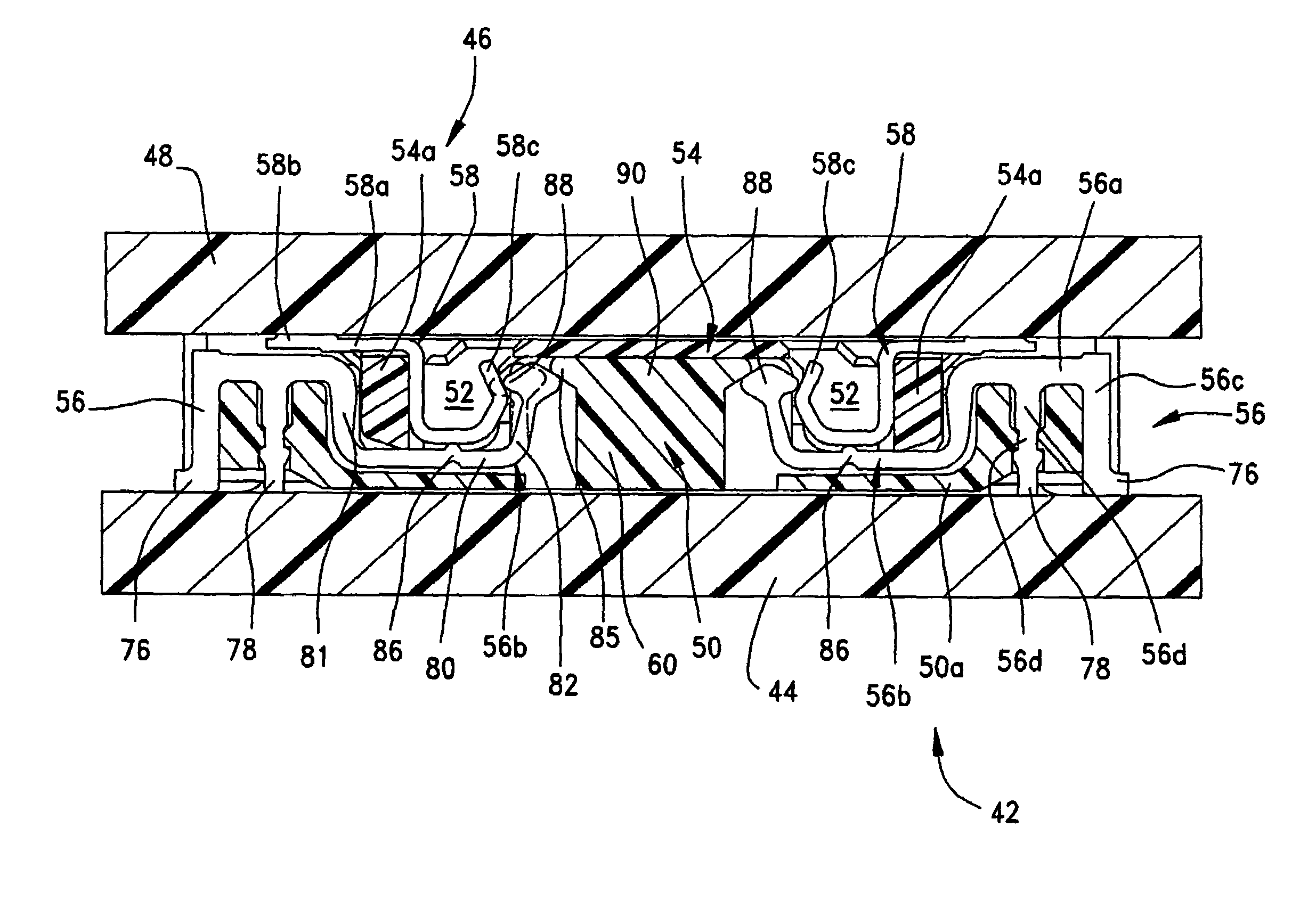
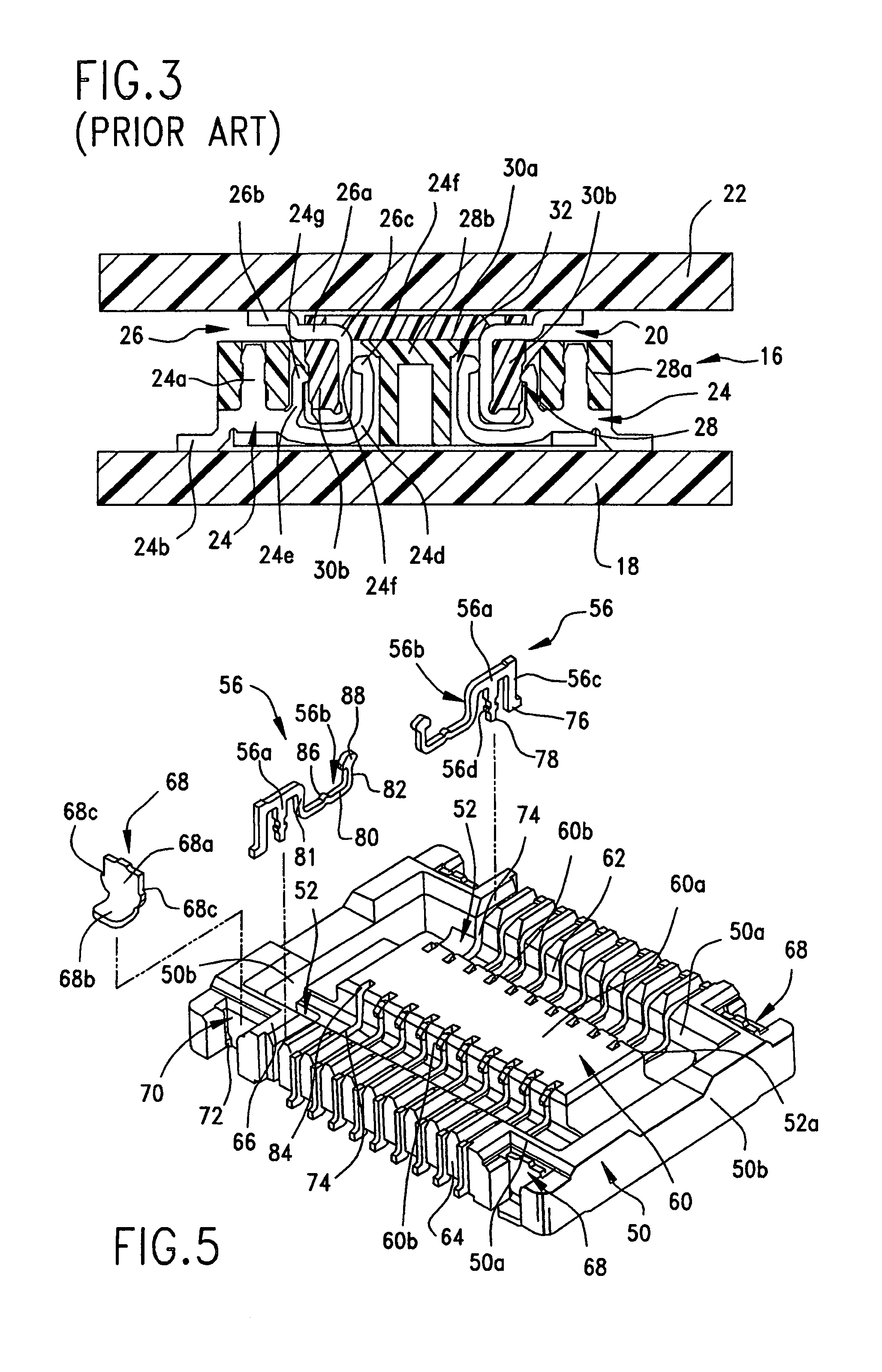
[0025]Referring to the drawings in greater detail, and first to FIG. 4, the invention is embodied in a board-to-board electrical connector assembly, generally designated 40, which includes a first electrical connector, generally designated 42, mounted on a first printed circuit board 44, and a second connector, generally designated 46, mounted on a second printed circuit board 48. The first connector includes a dielectric housing, generally designated 50, which includes a pair of opposite side walls 50a and a pair of opposite end walls 50b which combine to define a generally rectangular receptacle, generally designated 52. The receptacle has an insertion opening 52a. Second connector 46 includes a dielectric housing, generally designated 54, which includes a pair of opposite side walls 54a and a pair of opposite end walls 54b which combine to define a rectangular structure which is insertable into rectangular receptacle 52 of first connector 42. The housings of the connectors may be...


PUM


Abstract

An electrical connector is provided for use in a board-to-board electrical connector assembly and includes a dielectric housing for mounting on a first printed circuit board and having a receptacle for receiving a plug portion of a mating connector mounted on a second printed circuit board. A plurality of conductive terminals are mounted on the housing, and each terminal includes a contact arm extending into the receptacle. The contact arm has first and second contact portions projecting into the receptacle at different angles for engaging a terminal of the mating connector.

Description

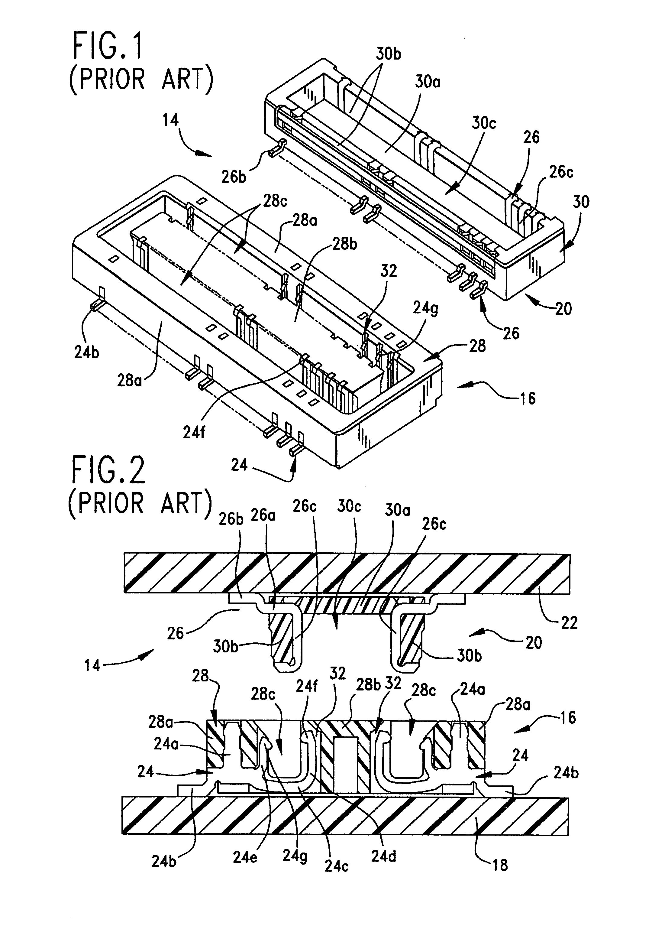
FIELD OF THE INVENTION[0001]This invention generally relates to the art of electrical connectors and, particularly, to a board-to-board electrical connector assembly having terminals with improved contacts.BACKGROUND OF THE INVENTION[0002]Miniature board-to-board electrical connector assemblies are known in the art. Conventionally, a first or receptacle connector is mounted on a first printed circuit board, and a plug or second connector is mounted on a second printed circuit board. The plug connector is inserted into the receptacle connector, with the two printed circuit boards in generally parallel relationship.[0003]FIGS. 1-3 show such an assembly as is known in the prior art. Specifically, a board-to-board electrical connector assembly, generally designated 14, includes a first connector, generally designated 16, mounted on a first printed circuit board 18, and a second connector, generally designated 20, mounted on a second printed circuit board 22. First connector 16 mounts a ...

Claims


Application Information

Patent Timeline
Patent Type & Authority Patents(United States)
IPC IPC(8): H01R12/00H01R12/14
CPCH01R12/57H01R23/72H01R12/52H01R12/716H01R12/7082H01R12/707H01R12/714
Inventor CHANG, WEI-SUNCHAO, PEI-CHANGHO, YI-TSE
Owner MOLEX INC
Learn More