
Vehicle vicinity image-processing apparatus and recording medium

a technology of image processing and vehicle, which is applied in the field of vehicle vicinity image processing apparatus and recording medium, can solve the problems of difficult to understand the relative positions of vehicles and objects, image displayed on the monitor, and objects outside the present field of vision of the camera, so as to simplify the computation of image processing and understand the effect of the relative position of the vehicle and the obj

Active Publication Date: 2008-01-08
DENSO CORP +1
View PDF17 Cites 54 Cited by
  • Summary
  • Abstract
  • Description
  • Claims
  • Application Information

AI Technical Summary

Benefits of technology

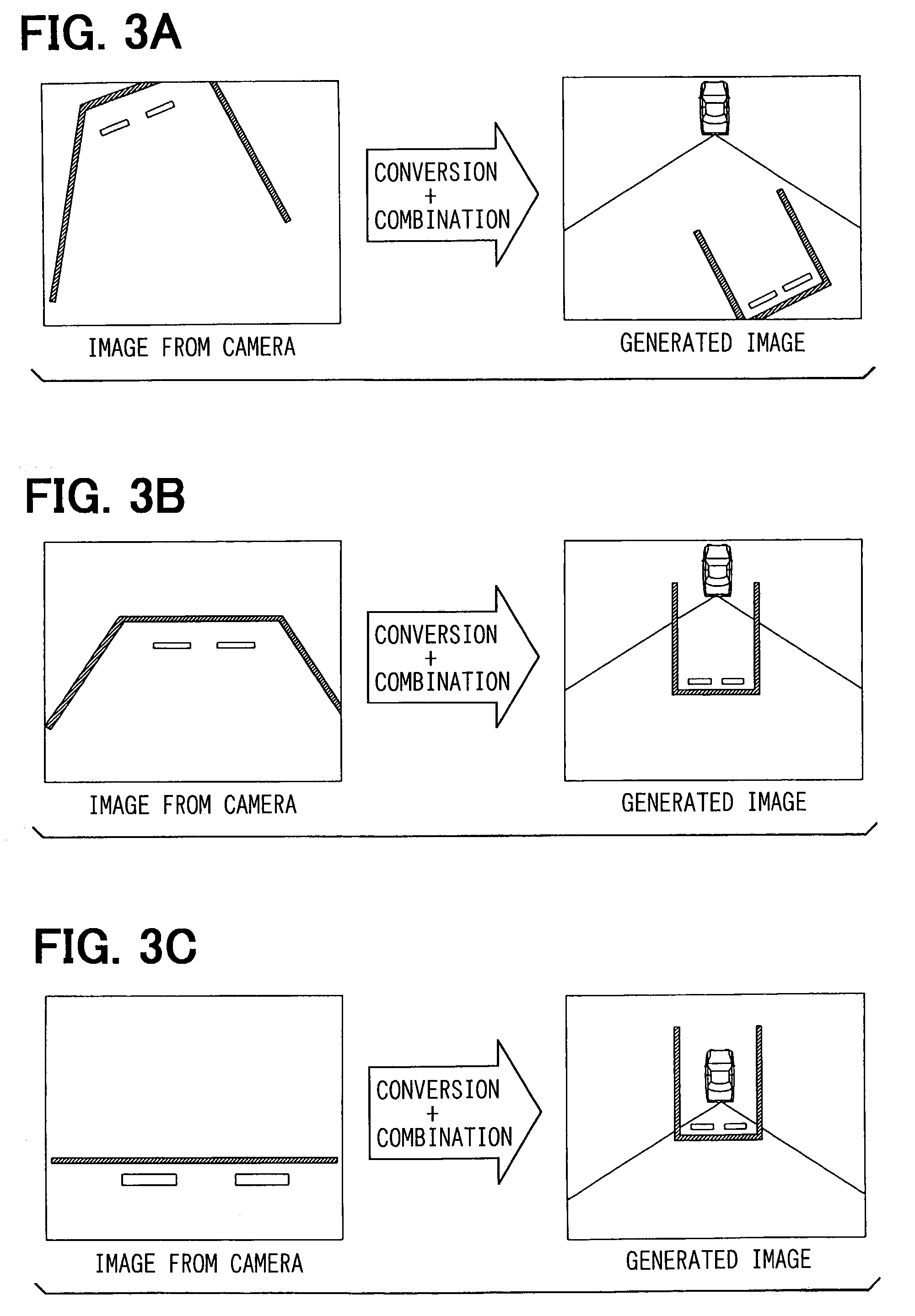
[0008]In this aspect of the invention, the difference of image between the first bird's-eye view image and the second bird's-eye view image is detected, and an image of this difference part (a part which was displayed before) is added to the second bird's-eye view image, whereby the situation around the vehicle can be understood more clearly. In this way, in this aspect of the invention, because an area having left the present field of vision of the for example camera can be displayed, there is the effect that for example when backing into a parking space, the maneuvering of the vehicle becomes extremely easy.
[0021]In the first and second aspects of the invention described above, when the composite image is displayed on the display means, an image of the vehicle maybe added to it. When the composite image showing the situation of the surroundings of the vehicle is displayed with an image showing the vehicle added to it like this, because the positional relationship between the vehicle and for example a parking space marking becomes clear, maneuvering of the vehicle becomes easy. Because for example the camera is fixed in a predetermined position on the vehicle, the position of the vehicle on the screen of for example the monitor is always the same. Therefore, the vehicle can be shown in a fixed position on the screen of the monitor, and the vehicle may even be represented on the screen of the monitor by printing or the like in advance. And, because the field of vision angle of the camera is also normally constant, not only the vehicle but also the field of vision angle of the camera (its left-right range) may be displayed on the screen of the monitor.

Problems solved by technology

According to the display apparatus, although the situation behind the vehicle can be understood to some extent, there has been the problem that it is difficult to understand the relative positions of the vehicle and objects (for example the marking of a parking space) in the image displayed on the monitor.
In the case of this technology, because the vehicle is shown in the bird's-eye view image, the positional relationship between objects displayed in the image and the vehicle is easier to understand than with the display apparatus which simply displays the picked-up image on the monitor as it is; however, there has been another problem that objects outside the present field of vision of the camera cannot be displayed.
Consequently, when for example the vehicle is being reversed into a parking space, because the marking of the parking space which have left the field of vision of the camera cannot be displayed, as before, there is the problem that maneuvering of backing the vehicle into the parking space is not easy.

Method used


Image

  • Vehicle vicinity image-processing apparatus and recording medium
  • Vehicle vicinity image-processing apparatus and recording medium
  • Vehicle vicinity image-processing apparatus and recording medium

Examples


first embodiment

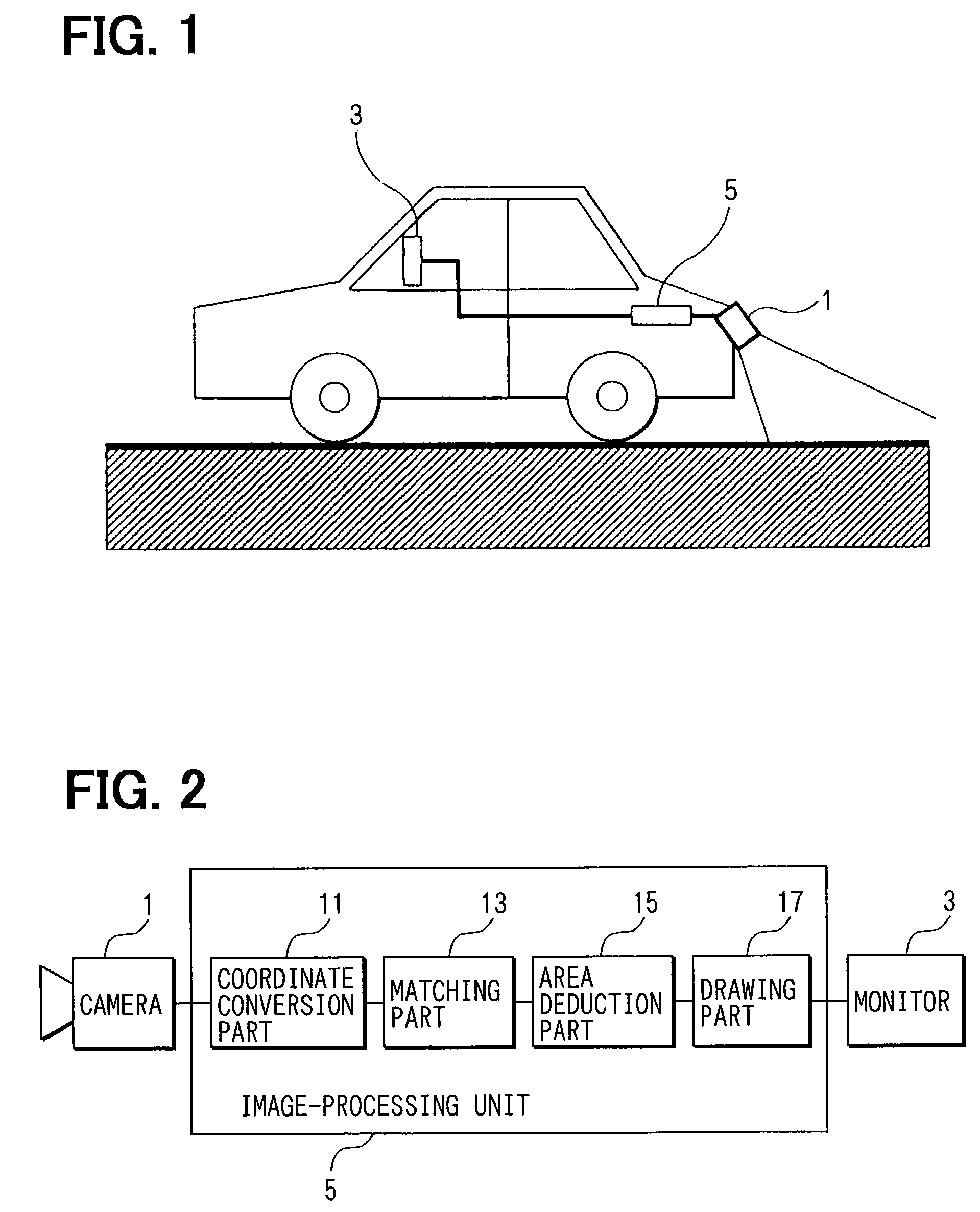
[0039]The basic system configuration of this embodiment will be explained using FIG. 1 and FIG. 2.

[0040]As shown in FIG. 1, the vehicle vicinity image-processing apparatus of this embodiment has a camera (for example a CCD camera) 1 mounted on the rear of an automobile, an in-vehicle monitor (for example a liquid crystal display) 3 mounted on a dashboard, and an image-processing unit 5 for carrying out image-processing.

[0041]As shown in FIG. 2, the image-processing unit 5 is an electronic device, having a microcomputer as a main part, for carrying out processing of image data, and, functionally, it has a coordinate conversion part 11 for performing a coordinate conversion on image data picked up by the camera 1 to create a bird's-eye view image; a matching part 13 for taking in two chronologically consecutive bird's-eye view images and comparing them; an area deduction part 15 for deducing an area having left the field of vision of the camera 1 from a non-matching part of the two bi...

second embodiment

[0063]A second embodiment of the invention will now be described, although parts the same as parts in the first embodiment will not be explained again here. In this embodiment, only image of a parking space marking and car stoppers and the like is extracted and drawn, and the image of the background is dispensed with.

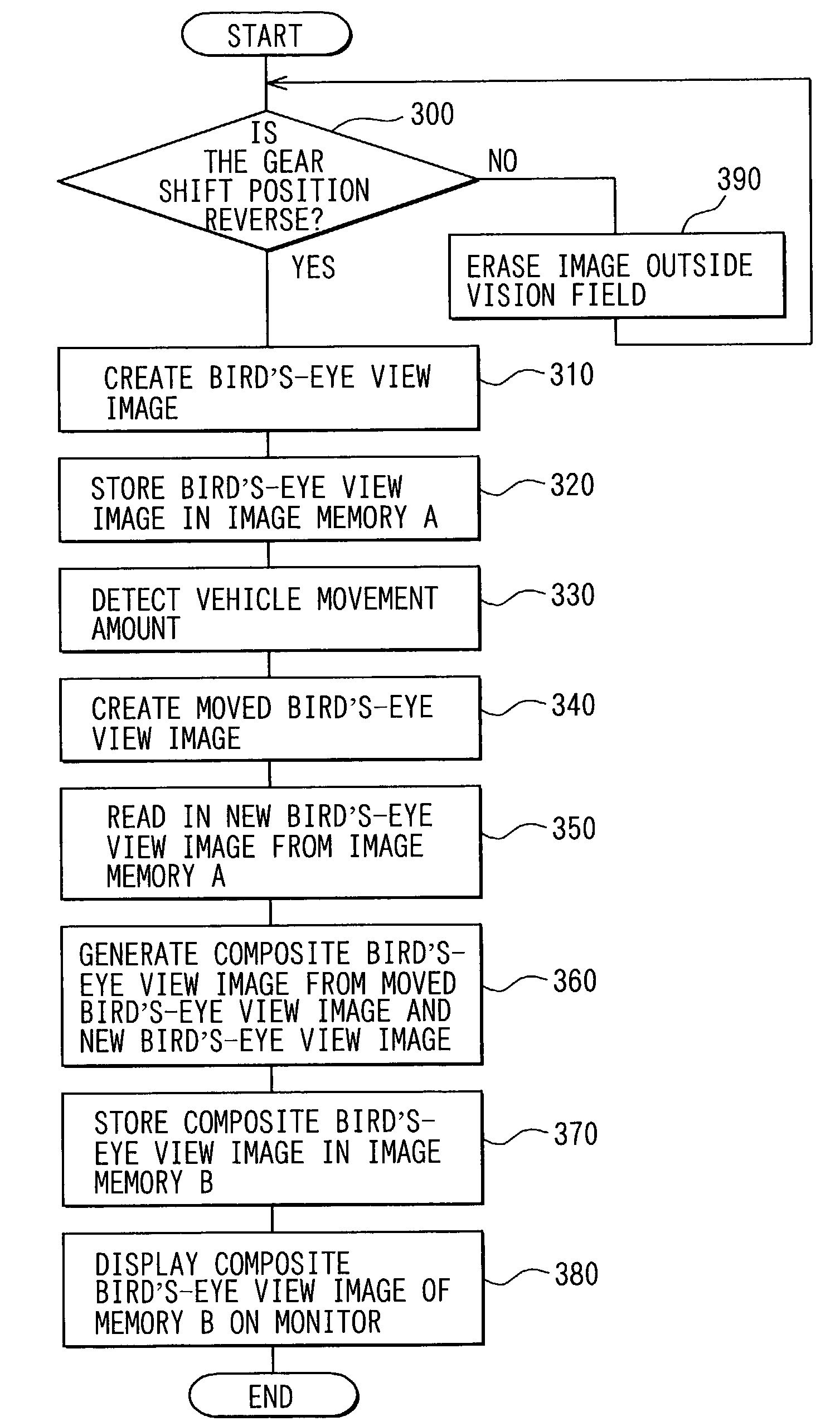
[0064]As shown in the flowchart of FIG. 8, first, in step 200, it is determined whether or not the gear shift position is Reverse. When an affirmative determination is made here processing proceeds to step 210, and when a negative determination is made processing proceeds to step 280.

[0065]In step 280, a previously drawn image of an area outside the field of vision of the camera is erased. In step 210, on the other hand, an image of the parking space marking and car stoppers and the like is extracted by means of binarization processing from the image picked up by the camera. Here, it is assumed that the parking space marking and the car stoppers are painted in white and...

third embodiment

[0069]A third embodiment will now be described. First, the basic system configuration of this embodiment will be explained, using FIG. 9 and FIG. 10.

[0070]As shown in FIG. 9, the vehicle vicinity image-processing apparatus of this embodiment has a camera (for example a CCD camera) 21 mounted on the rear of the vehicle; an in-vehicle monitor (for example a liquid crystal display) 23 mounted on the dashboard of the vehicle; a vehicle speed sensor 25 for detecting a vehicle speed; a yaw rate sensor 27 for detecting a yaw rate; and an image-processing unit 29 for carrying out image-processing.

[0071]The image-processing unit 29, as shown in FIG. 10, is an electronic device, having a microcomputer as a main part, for carrying out processing of image data, and has a coordinate conversion part (bird's-eye view image conversion circuit) 31 for performing coordinate conversion of image data picked up by the camera 21; an image memory A for temporarily storing image data of a created bird's-ey...


PUM


Abstract

The present invention provides a vehicle vicinity image-processing apparatus and a recording medium capable of deducing a scene having left the field of vision of a camera mounted on the rear of a vehicle and drawing an image of the area behind the vehicle which includes this deduced part. An image-processing unit 5 first coordinate-converts a picked-up image to create a bird's-eye view image. Two chronologically consecutive bird's-eye view images are created as the bird's-eye view image, and a matching area of the two images is extracted. On the basis of this matching area, a moved area which has left the present field of vision of the camera 1 is extracted. An image of the matching area and the moved area is then drawn on a monitor 3. By this means, it is possible to draw an image including a scene which has left the present field of vision of the camera 1.

Description

TECHNICAL FIELD[0001]This invention relates to a vehicle vicinity image-processing apparatus and a recording medium for picking up and displaying on a monitor an image of for example the area behind a vehicle.BACKGROUND ART[0002]As an apparatus for displaying the scene behind a vehicle, a display apparatus which outputs unchanged to a monitor an image from a camera mounted on the rear of the vehicle has been known. According to the display apparatus, although the situation behind the vehicle can be understood to some extent, there has been the problem that it is difficult to understand the relative positions of the vehicle and objects (for example the marking of a parking space) in the image displayed on the monitor.[0003]Separately from such a display apparatus, in Japanese Unexamined Patent Publication No. H.10-211849, technology which converts an image picked up by a rear camera (a rear camera image) into a bird's-eye view image and displays in this bird's-eye view image the vehi...

Claims


Application Information

Patent Timeline
Patent Type & Authority Patents(United States)
IPC IPC(8): G06K9/36B60Q1/00H04N7/18H04N9/47G09B29/00B60R1/00B60R21/00G06T1/00G06T3/00G06T7/00H04N5/225
CPCB60R1/00G06T3/00G06T7/0024H04N7/18B60R2300/302B60R2300/607B60R2300/806B60T2201/10G06T7/30B60R1/27
Inventor YANAGAWA, HIROHIKOISHIKAWA, TETSURIIMANISHI, MASAYUKI
Owner DENSO CORP
Learn More