
Infusion device for medical use

a technology for infusion devices and medical devices, which is applied in the direction of process and machine control, instruments, etc., can solve the problems of increasing the weight of the device structure and the total cost of the infusion line, and achieve the effect of simple structur

Inactive Publication Date: 2008-01-08
GAMBRO LUNDIA AB
View PDF74 Cites 195 Cited by
  • Summary
  • Abstract
  • Description
  • Claims
  • Application Information

AI Technical Summary

Benefits of technology

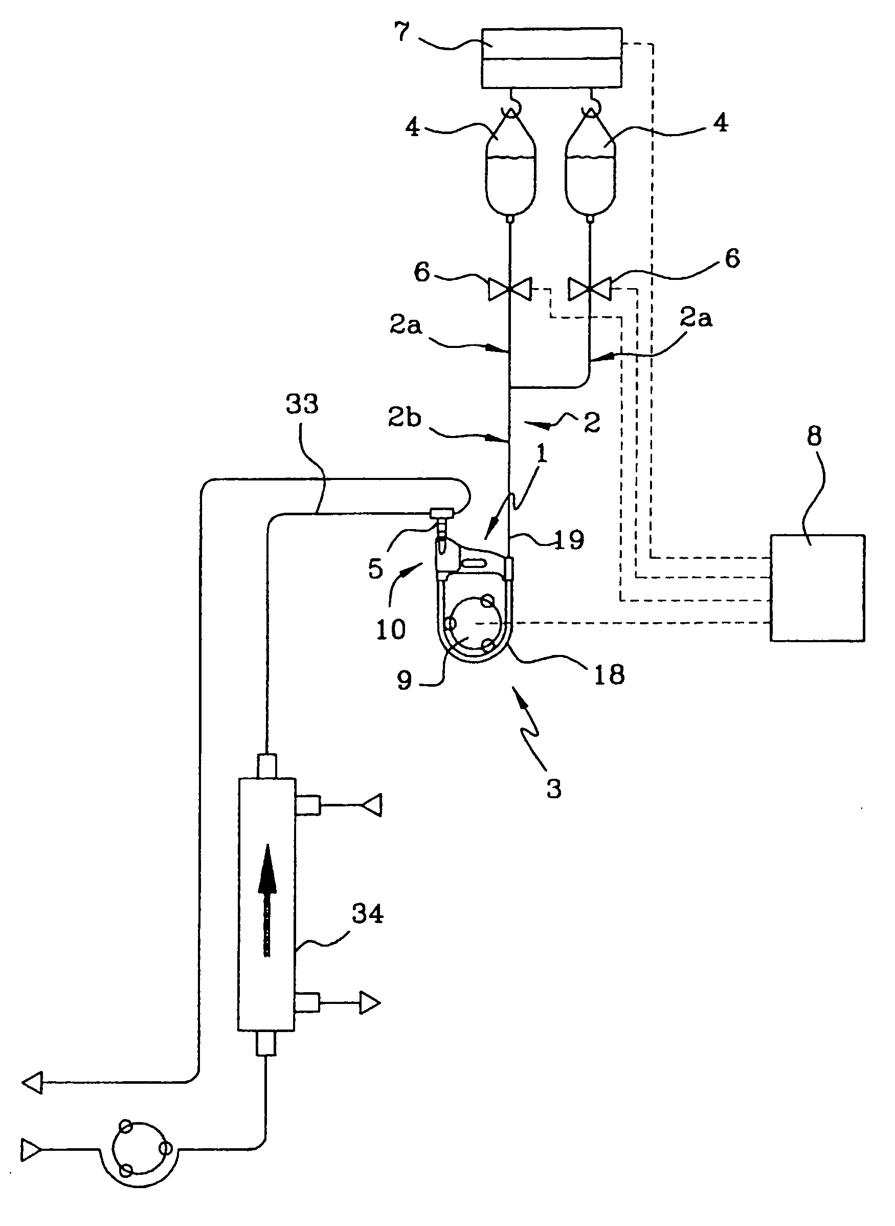
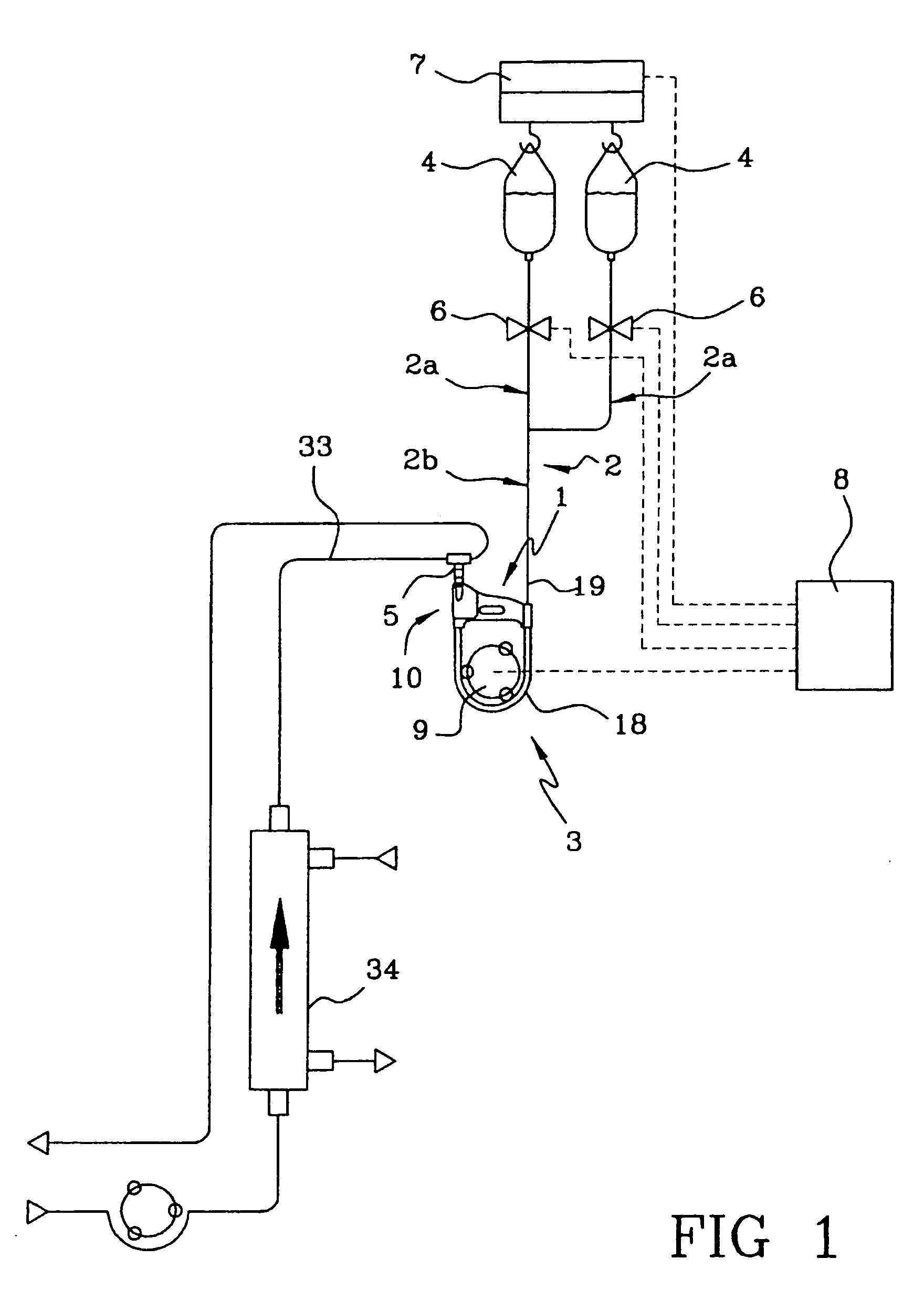
[0024]In this situation, the object of the present invention is to provide a novel infusion device for the infusion of a liquid from a bag using a line having a very simple structure and overcoming all the drawbacks described above.
[0025]In particular, an object of the present invention is to provide an infusion device which does not require the use of a chamber for collecting the fluid upstream of the infusion point, and which does not require the presence of any optical or ultrasonic level sensor.
[0026]In particular, an object of the present invention is to combine efficiently, in an infusion line, the presence of a balance operating on the infusion bag with the presence of a special system capable of continuously preventing the passage of air to the patient during the detection of the end of infusion condition, in such a way as to make the whole infusion line extremely simple, efficient and reliable, so that there is theoretically no need to have further safety systems (clamps or other devices) for stopping the flow along the line.
[0027]Finally, an object of the present invention is to provide an infusion line which allows a plurality of bags to be incorporated, with a simple means of changing from one bag to the next when the liquid contained in each infusion bag is used up.

Problems solved by technology

The various lengths of tubing forming the infusion line and the collection chamber then undergo a rather complicated assembly process which considerably increases the total costs of the infusion line.
Furthermore, in the case of infusion lines interacting with level sensors, it is necessary to use optical or acoustic detectors which further increase the weight of the structure of the device.

Method used


Image

  • Infusion device for medical use
  • Infusion device for medical use
  • Infusion device for medical use

Examples


second embodiment

[0079]In the second embodiment, the continuous fluid separator 10 includes a check valve 36 which is predisposed to prevent back-flow in an opposite direction to the flow direction of the extracorporeal fluid.

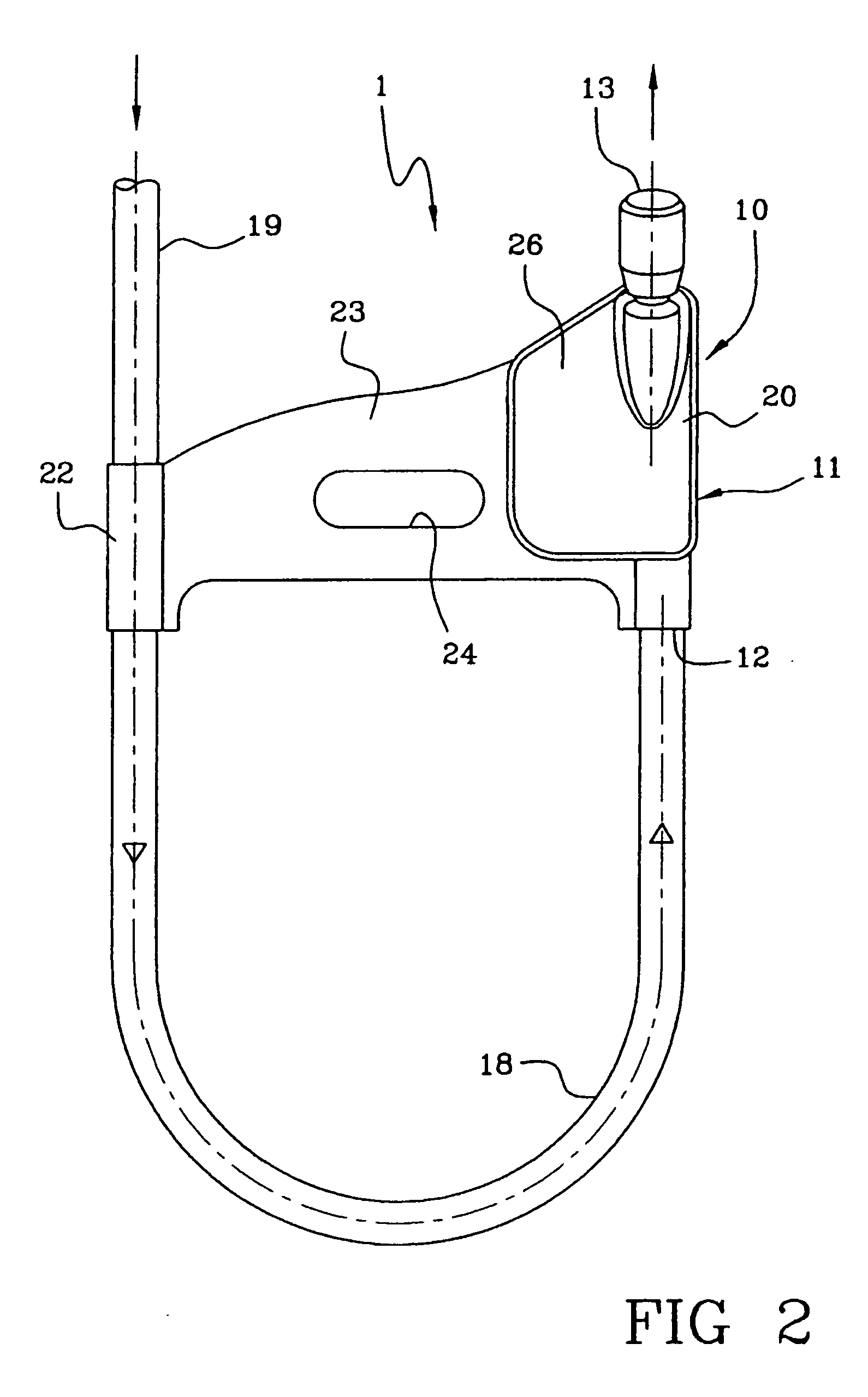
[0080]The check valve 36, or one-way valve, is predisposed along the liquid portion line after the liquid has already been separated from the gas portion by the continuous fluid separator 10. The check valve 36 is arranged internally of the separator containing body 11, in a zone comprised between the separator selector means 15 and the first outlet 13 (liquid outlet).

[0081]The check valve 36 comprises a mobile obturator organ 37 operating on a liquid passage mouth 35, through which the liquid portion passes. The obturator organ 37 is disc-shaped and is made of an elastomer material (for example silicone). The obturator organ 37 is mobile inside a chamber which, when the obturator is open, communicates on one side thereof with the fluid passage mouth 35. In the presence of a fl...

first embodiment

[0084]As in the first embodiment, the containing body 11 internally affords a fluid passage 27 between the inlet 12 and the first outlet 13. This fluid passage 27 has an upstream portion 27a, comprised between the inlet 12 and the hydrophilic membrane 16, and a downstream portion 27b, comprised between the hydrophilic membrane 16 and the first outlet 13. The base wall 26a, on which the passage mouth 35 is afforded, delimits the downstream portion 27b of the fluid passage.

[0085]The passage mouth 35 is situated in a lateral end zone of the base wall 26a (see FIG. 15), which lateral end zone is opposite to the lateral end position in which the fluid inlet 12 is situated in the containing body 11.

[0086]As illustrated in FIG. 15, the projections 32, arranged on the internal side of the base wall 26a, are subdivided into a first group of projections, which reach as far as the passage mouth 35, where the projections 32 are conformed in lines, parallel to one another and extending in a hori...


PUM


Abstract

An infusion device for medical use has a container designed to hold a specified quantity of a liquid to be infused into a patient, a weighing device associated for operation with the container to measure the weight of the container and emit a corresponding signal, a transport line connected to the container, a pump, and a control unit associated with the weighing device and with the pump. The control unit is capable of detecting the end of infusion condition and of commanding the pump to stop the transport of fluid. A separator for continuously separating fluid into a gaseous portion and a liquid portion operates in the infusion line downstream of the pump and prevents the infusion of gas during the stopping transient of the pump at the end of infusion.

Description

BACKGROUND OF THE INVENTION[0001]The present invention relates to an infusion device for medical use.[0002]In particular, the device of the invention is used in apparatus for the extracorporeal treatment of blood, for example apparatus for dialysis and / or plasmapheresis, in order to provide an infusion line which can be connected to an extracorporeal blood circuit associated with the aforementioned apparatus; the device in question can also be used for forming an infusion line which can be connected directly to the patient's vascular system.[0003]As is known, a conventional infusion line comprises at least one length of tubing designed to connect a bag containing a specified infusion liquid to an extracorporeal blood circuit or directly to a patient through conventional access means such as needles, catheters or the like.[0004]A pump, of the peristaltic type for example, can be provided on the infusion line for moving the infusion fluid in the desired way. For example, U.S. Pat. No....

Claims


Application Information

Patent Timeline
Patent Type & Authority Patents(United States)
IPC IPC(8): A61M37/00A61N1/30A61M1/00A61M5/165A61M5/168
CPCA61M5/165A61M5/16845A61M5/16895A61M5/36
Inventor DELNEVO, ANNALISACALEFFI, LUCA
Owner GAMBRO LUNDIA AB
Learn More