
Electric portable power tool with rotatable guard

a portable power tool and rotatable technology, applied in the field of manual operation of electric machine tools, can solve the problems of guard not being fixed to the collar with a sufficient degree of reliability, cutting wheel shattering, clamping screw wear,

Inactive Publication Date: 2007-12-25
ROBERT BOSCH GMBH
View PDF16 Cites 62 Cited by
  • Summary
  • Abstract
  • Description
  • Claims
  • Application Information

AI Technical Summary

Benefits of technology

The present invention is a manually operated machine tool with a rotating guard that can be adjusted to different positions without needing an auxiliary tool. The clamping element is only used during initial installation and can be reset or readjusted if wear occurs. The clamping element uses a toothed section and a ratchet to prevent the guard from rotating when parts are hurled from a shattered tool. The ratchet is designed to self-lock if the tool shatters. The toothed section has sawtooth-shaped teeth with steeply sloped tooth flanks and shallowly sloped tooth backs. The ratchet can be pivoted away from the clamp to release the locking mechanism and allow for rotation in both directions. The clamp is secured to the collar using a circumferential groove / spring connection. The collar can also have at least one axial groove that prevents the guard from being used on other types of manual operated electric machine tools.

Problems solved by technology

For example, when a cutting wheel jams in the work piece, the cutting wheel can shatter.
Adjusting the guard by loosening and tightening the clamping screw with the required auxiliary tool is not only troublesome so that the procedure of adjusting the guard to the proper working position is often omitted, but also, over the long term, subjects the clamping screw to wear so that the guard can no longer be fixed to the collar with a sufficient degree of reliability and no longer assures sufficient protection of the operator if a tool shatters.

Method used


Image

  • Electric portable power tool with rotatable guard
  • Electric portable power tool with rotatable guard
  • Electric portable power tool with rotatable guard

Examples


Embodiment Construction

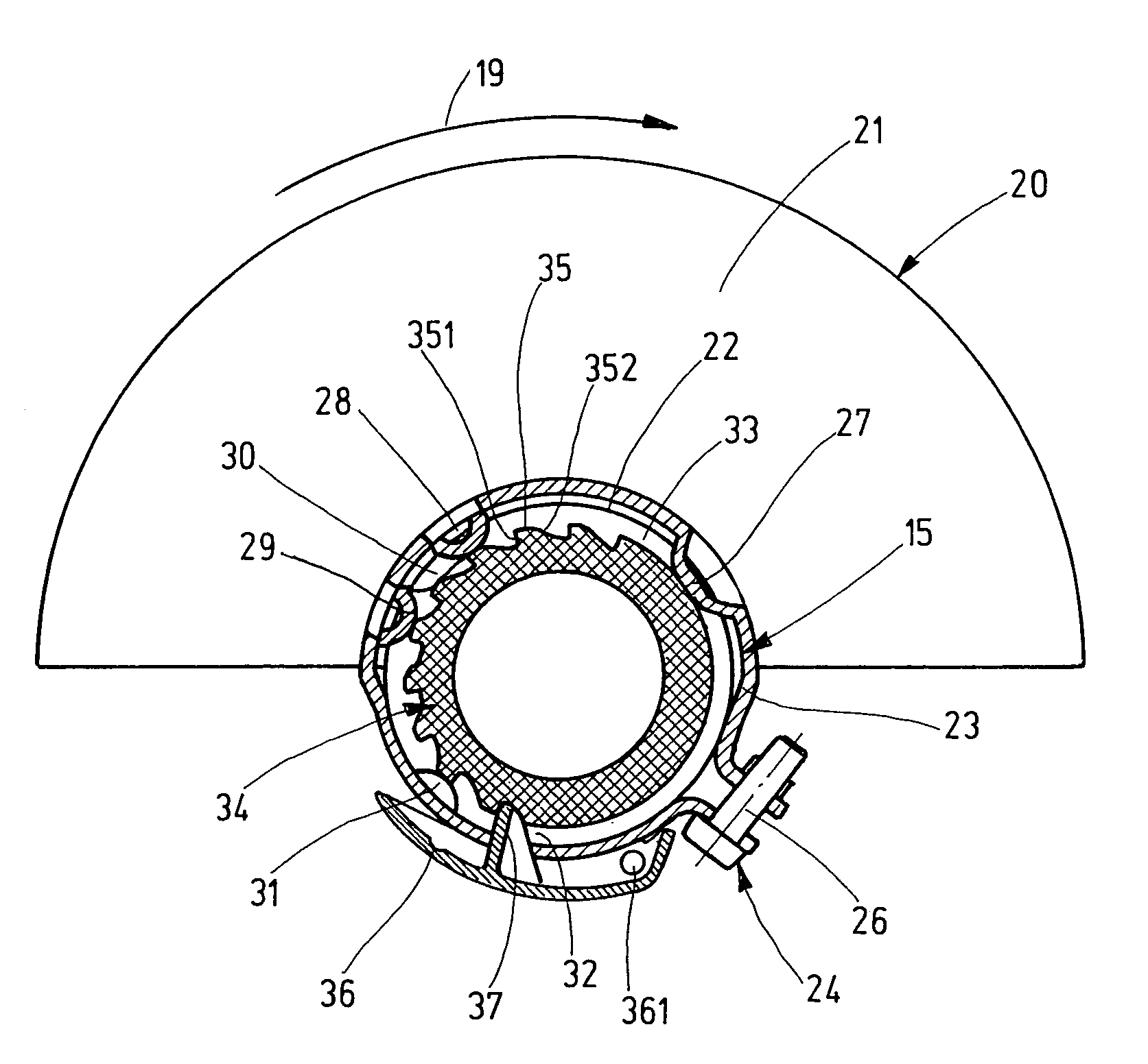
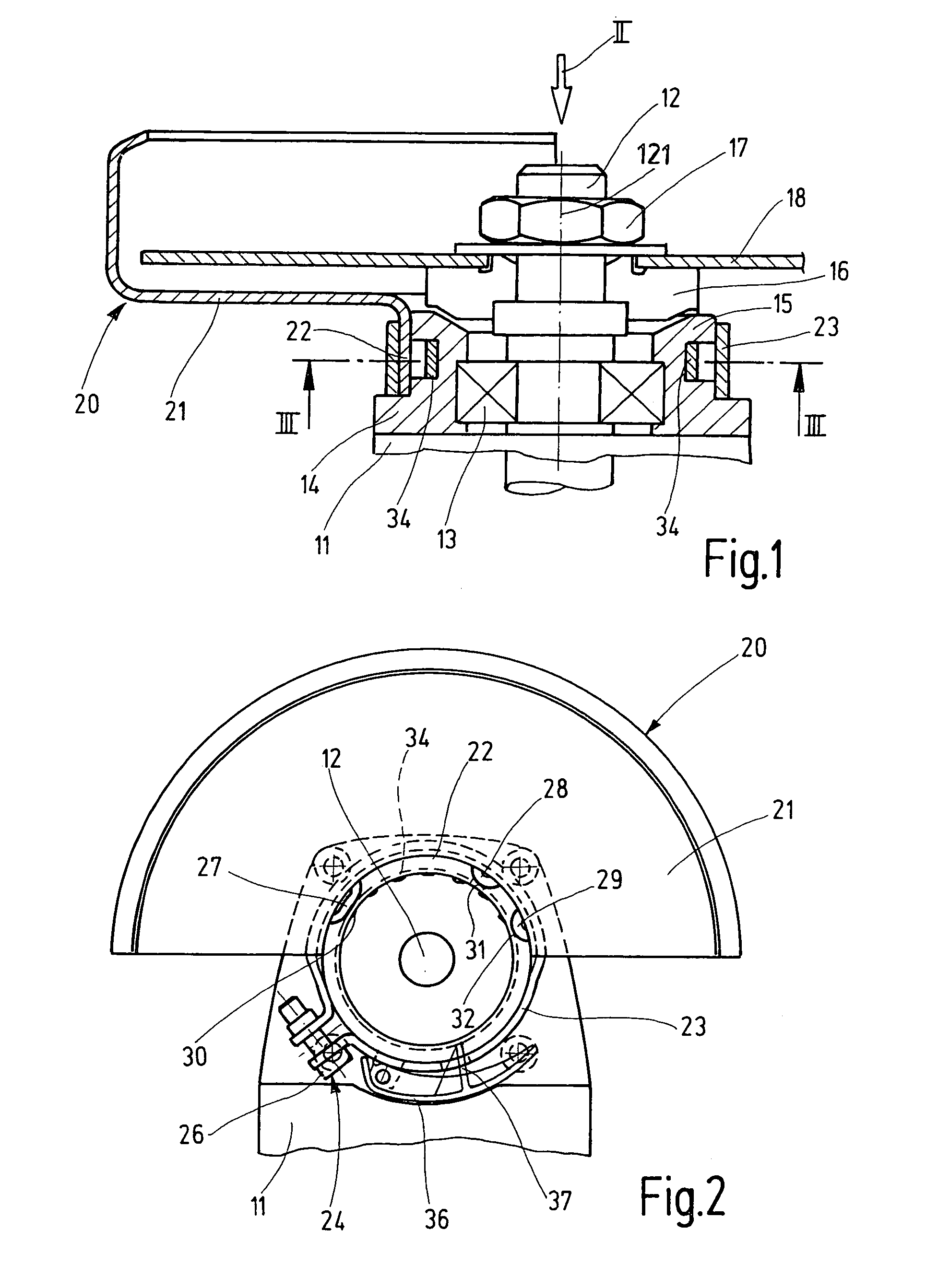
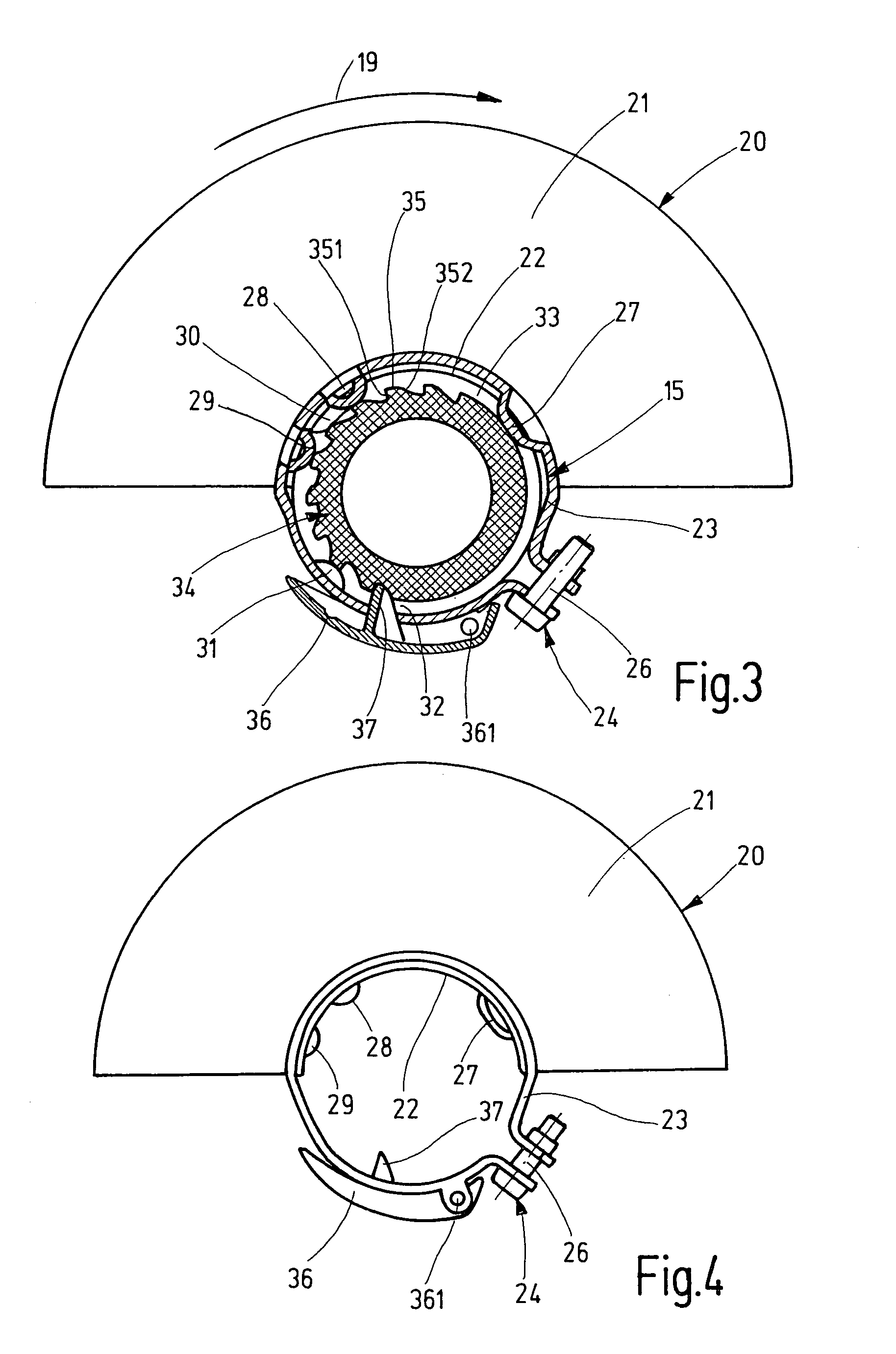
[0020]The angle grinder, which is depicted in a longitudinally sectional detail view in FIG. 1 as an exemplary embodiment for a generic manually operated electric machine tool with a disk-shaped rotating tool, has a machine housing 11 that contains an electric motor that drives a drive spindle 12 protruding from the machine housing 11 and connected to the motor via a transmission. Close to the point at which it exits the machine housing 11, the drive spindle 12 is supported in rotary fashion by means of a radial bearing 13 in a housing flange 14 on which a hollow, cylindrical collar 15 is embodied, which is coaxial to the axis 121 of the drive spindle 12. The drive spindle 12 supports a socket flange 16 that is secured to it in a rotationally fixed manner, to which a grinding or cutting wheel 18—as an exemplary embodiment for a generic disk-shaped, rotating tool—can be clamped by means of a threaded nut 17. In order to protect the operator, the grinding or cuffing wheel 18 is covere...


PUM


Abstract

A manually operated electric machine tool for a disk-shaped rotating tool (18), having a machine housing (11) from which a drive spindle (12) for the tool (18) protrudes and on which a hollow cylindrical collar (15) is embodied coaxial to the drive spindle (12), and having a guard (20) that is detachably connected to the machine housing (11) and is designed to at least partially cover the tool (18), which guard can be mounted to and fixed in relation to the collar (15) by means of a clamp (23) with a clamping element (24). To set the guard (20) in desired rotation positions in relation to the machine housing (11) without using an auxiliary tool, and to secure the guard (20) in any rotation position, the clamp (23) is secured to the collar (15) in a rotating fashion and a manually releasable locking mechanism is provided between the clamp (23) and the collar (15) (FIG. 1).

Description

CROSS-REFERENCE[0001]The invention described and claimed hereinbelow is also described in PCT / DE 03 / 03625, filed Oct. 31, 2003 and DE 102 59 520.8, filed Dec. 19, 2002. This German Patent Application, whose subject matter is incorporated here by reference, provides the basis for a claim of priority of invention under 35 U.S.C 119 (a)–(d).BACKGROUND OF THE INVENTION[0002]The present invention is based on a manually operated electric machine tool for a disk-shaped, rotating tool.[0003]In manually operated electric machine tools of this kind, the purpose of the guard is to protect the user from sparks and material particles that are hurled outward from the rotating tool, e.g. a grinding wheel or cutting wheel, during operation. The guard should also protect the user in the event that the tool breaks. For example, when a cutting wheel jams in the work piece, the cutting wheel can shatter. In this case, the guard must prevent fragments of the shattered cutting wheel from coming near the ...

Claims


Application Information

Patent Timeline
Patent Type & Authority Patents(United States)
IPC IPC(8): B24B23/00B23Q11/06B23Q16/02B24B23/02B24B27/08B24B55/05
CPCB23Q11/06B23Q16/025B24B55/052B24B27/08B24B23/02
Inventor WIKER, JUERGEN
Owner ROBERT BOSCH GMBH
Learn More