
Implement

a technology of implements and implements, applied in the field of manufacturable implements, to achieve the effect of adequate cooling air and simple manufacturing

Active Publication Date: 2007-12-25
ANDREAS STIHL AG & CO KG
View PDF20 Cites 15 Cited by
  • Summary
  • Abstract
  • Description
  • Claims
  • Application Information

AI Technical Summary

Benefits of technology

[0003]The object of the invention is to create a manually operated tool with a fan wheel cover which is simple to manufacture and which guarantees an adequate supply of cooling air.
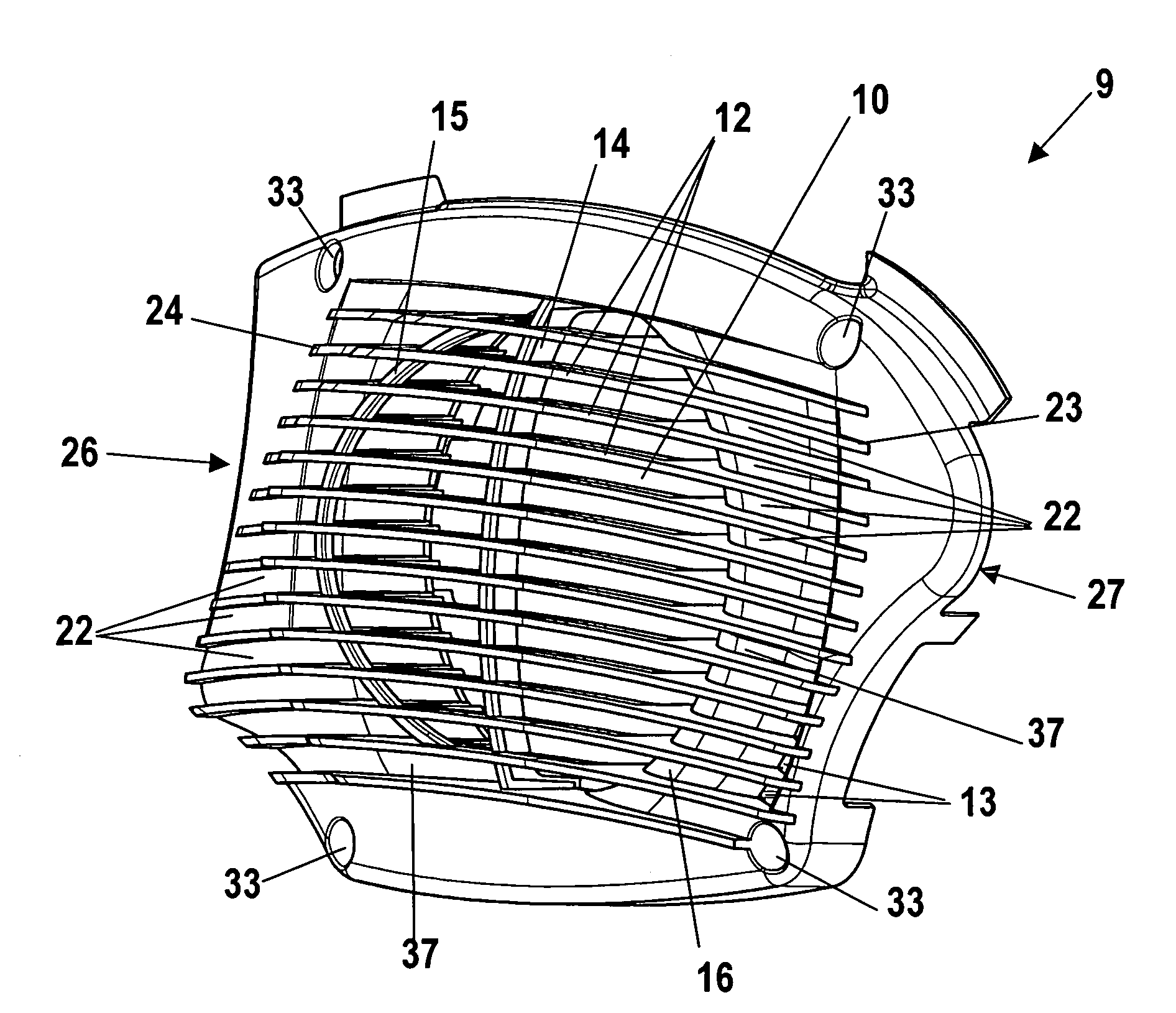
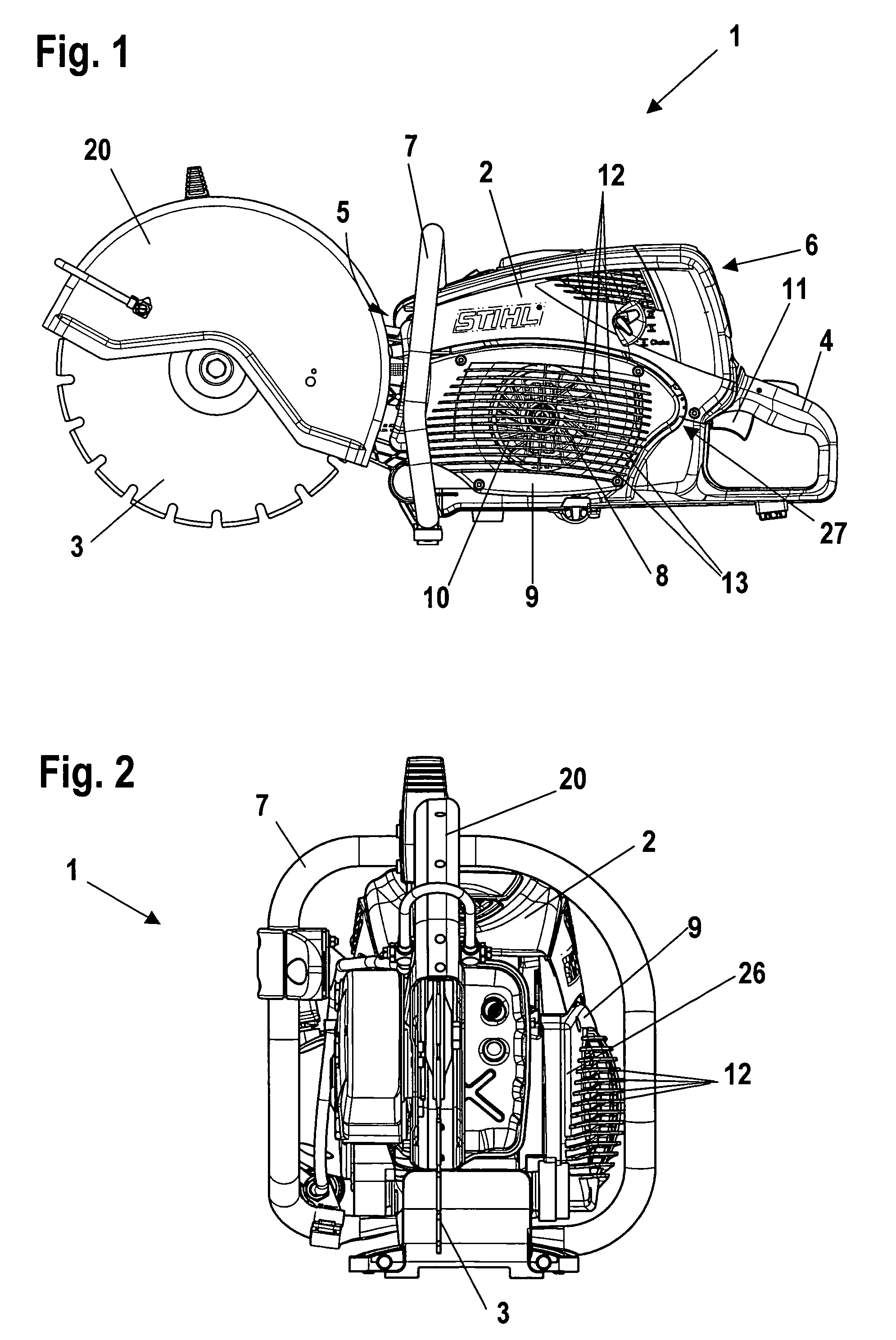
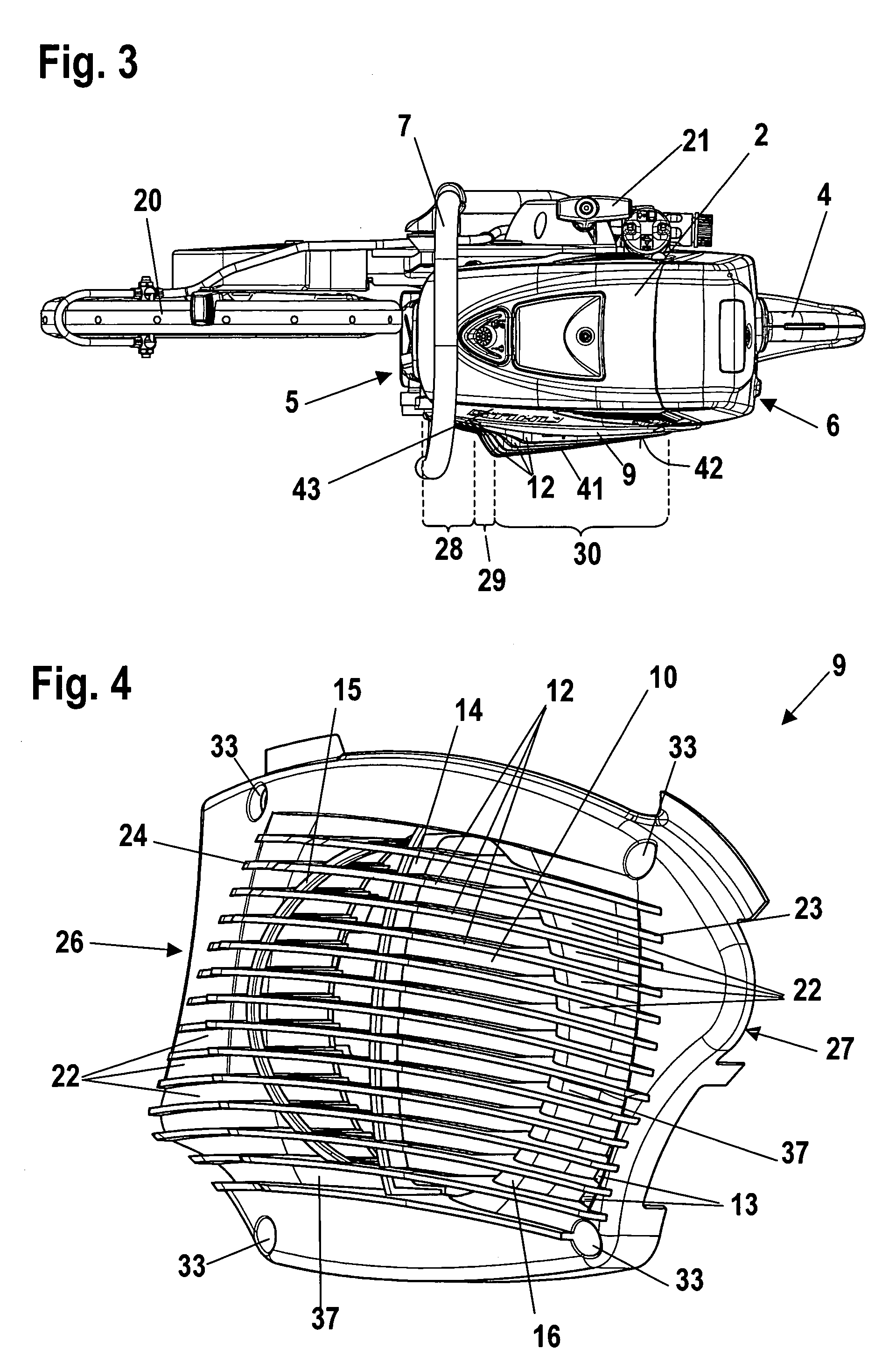
[0006]The intake surface in the second area advantageously faces the front face of the housing. This orientation means that the intake surface in the second area faces away from the body of the operator, thereby preventing the aspiration of clothing or similar items. Advantageously positioned adjacent to the second area of the intake surface is a third area, an edge being formed between the third area and the second area. The edge, too, prevents clothing or similar items aspirated in the third area from resting against the second area. In addition, the formation of an edge between the two areas prevents fabrics, leather or other materials from coming into contact with the edge. The upper face of a rib in the second area advantageously lies at an angle of 15° to 90°, in particular 25° to 75°, to the upper face in the third area. This arrangement means, in particular, that the angle decreases from a central rib to outer ribs. As a result, the shape of the intake surface is curved around the periphery of the housing and the presence of an edge does not therefore impair the handling of the tool. The height of the ribs advantageously decreases continuously in a third area adjacent to the second area. In this arrangement, the third area is in particular an area of the ribs facing the rear face of the housing. Due to the flat design of the ribs and the continuous increase in rib height in the third area, the ribs form an approximately flat surface. The operator is able to hold this surface of the tool against his body during operation in such a manner as to ensure good handling. At the same time, the presence of the second area ensures an adequate supply of both cooling and combustion air to the drive motor. The tool advantageously has a gripper bar or tubular handle which spans the housing in the vicinity of the front face of the housing, and a rear handle which is fixed to the rear face of the housing. In implements with a rear handle, in particular, the operator is likely to rest the area of the implement near the fan wheel cover against his body since the rear face of such an implement does not offer a sufficiently large surface on which to rest it. Due to the flat design of the ribs in the first area and the positioning of the second area adjacent to the first area, it is possible to guarantee good access to the tubular handle. The ribs between the first and second areas are positioned sufficiently far from the handle. At the same time, the positioning of the handle shields the second area to a certain extent, and it is therefore unlikely that clothing will be aspirated in the second area.
[0007]In order to guarantee adequate air intake, an opening positioned in the fan wheel cover and connected to the intake opening by at least one channel runs into said channel. If the fan wheel cover is inadvertently covered, air from inside the housing is delivered through the opening into a channel formed between two ribs and from there back into the housing through the intake opening. The air taken in from the housing is taken in from the area of the carburetor chamber and / or through the vibration gap from outside the housing, for example. The fact that the channel is formed of ribs, i.e. is open to the outside of the fan wheel cover, means that no additional sliders are required to create channels. The fan wheel cover can thus be manufactured simply with simply designed tools using an injection molding process.

Problems solved by technology

In implements with a rear handle, in particular, the operator is likely to rest the area of the implement near the fan wheel cover against his body since the rear face of such an implement does not offer a sufficiently large surface on which to rest it.

Method used


Image

  • Implement
  • Implement
  • Implement

Examples


Embodiment Construction

[0021]The cut-off machine (1) shown in FIG. 1 has a housing (2) containing a drive motor (not illustrated) providing the rotary drive for a cutting wheel (3). The cutting wheel (3) is partially enclosed by a protective cover (20). The cutting wheel (3) is positioned adjacent to the front face (5) of the housing (2). As is also shown in FIG. 2, the cut-off machine (1) has a gripper bar or tubular handle (7) which spans the housing (2) in the area of the front face (5). Positioned on the rear face (6) of the housing facing away from the front face (5) is a rear handle (4) to which is fixed a trigger switch (11) for operating the drive motor. The cut-off machine (1) has a fan wheel (8) which is driven by the drive motor. The fan wheel (8) is, in particular, fixed to the crankshaft of the drive motor.

[0022]The fan wheel (8) is positioned behind a fan wheel cover (9) which separates the fan wheel (8) from the outside of the housing. In the area of the fan wheel (8), the fan wheel cover (...


PUM

PropertyMeasurementUnit
Angleaaaaaaaaaa
Angleaaaaaaaaaa
Angleaaaaaaaaaa

Abstract

A manually operated implement comprising a housing for accommodating a drive motor that drives a tool. A fan wheel is disposed in the housing and is driven by the drive motor. A fan wheel cover covers the fan wheel toward the outer side of the housing. Ribs are disposed on the outer surface of the fan wheel cover and span an intake opening of the fan wheel cover in the vicinity of the fan wheel. Beyond the intake opening, the ribs form channels, and upper faces of the ribs that face away from the outer surface of the fan wheel cover form an intake face that in a second area of the ribs is disposed transverse to the outer surface of the fan wheel cover.

Description

BACKGROUND OF THE INVENTION[0001]The invention relates to a manually operated implement, in particular, a cut-off machine or similar device.[0002]A power saw with a fan wheel cover in which air is taken in through a grill is known from U.S. Pat. No. 5,168,837. In order to allow the emergency intake of air if the grill is covered, channels are provided beneath the grill which extends as far as a rear wall of the fan wheel cover. Since the channels run between the grill and an air guide wall, the manufacture of the fan wheel cover using an injection molding process requires costly sliders.SUMMARY OF THE INVENTION[0003]The object of the invention is to create a manually operated tool with a fan wheel cover which is simple to manufacture and which guarantees an adequate supply of cooling air.[0004]This object is achieved by means of a manually operated implement comprising a housing for accommodating a drive motor that drives a tool; a fan wheel disposed in the housing and driven by the...

Claims


Application Information

Patent Timeline
IPC IPC(8): F01P1/02F02B77/04B23D47/00B24B27/08B24B55/05B25F5/02F01P5/02
CPCB23D47/00B24B55/052B24B27/08F01P5/02B24B23/02F01P5/06F02B63/02
Inventor RIEHMANN, JENS
Owner ANDREAS STIHL AG & CO KG
Learn More