
Silk flower holder

a silver and flower holder technology, applied in the field of cemeteries, can solve the problems of prone to blowing away the entire flower assembly

Active Publication Date: 2007-12-25
D R BROEL
View PDF20 Cites 11 Cited by
  • Summary
  • Abstract
  • Description
  • Claims
  • Application Information

AI Technical Summary

Benefits of technology

"The patent describes a holder for silk flowers that has multiple arms that stick out from it. The holder has a cavity with a hole in it, and there is a prong that sticks out from the holder and goes into the hole. This design helps to hold the silk flowers securely and prevents them from getting damaged during transportation."

Problems solved by technology

If the holder is too small, the entire flower assembly is prone to be blown away by high winds or it simply floats upwardly when the flower container fills with water.

Method used


Image

  • Silk flower holder
  • Silk flower holder
  • Silk flower holder

Examples


Embodiment Construction

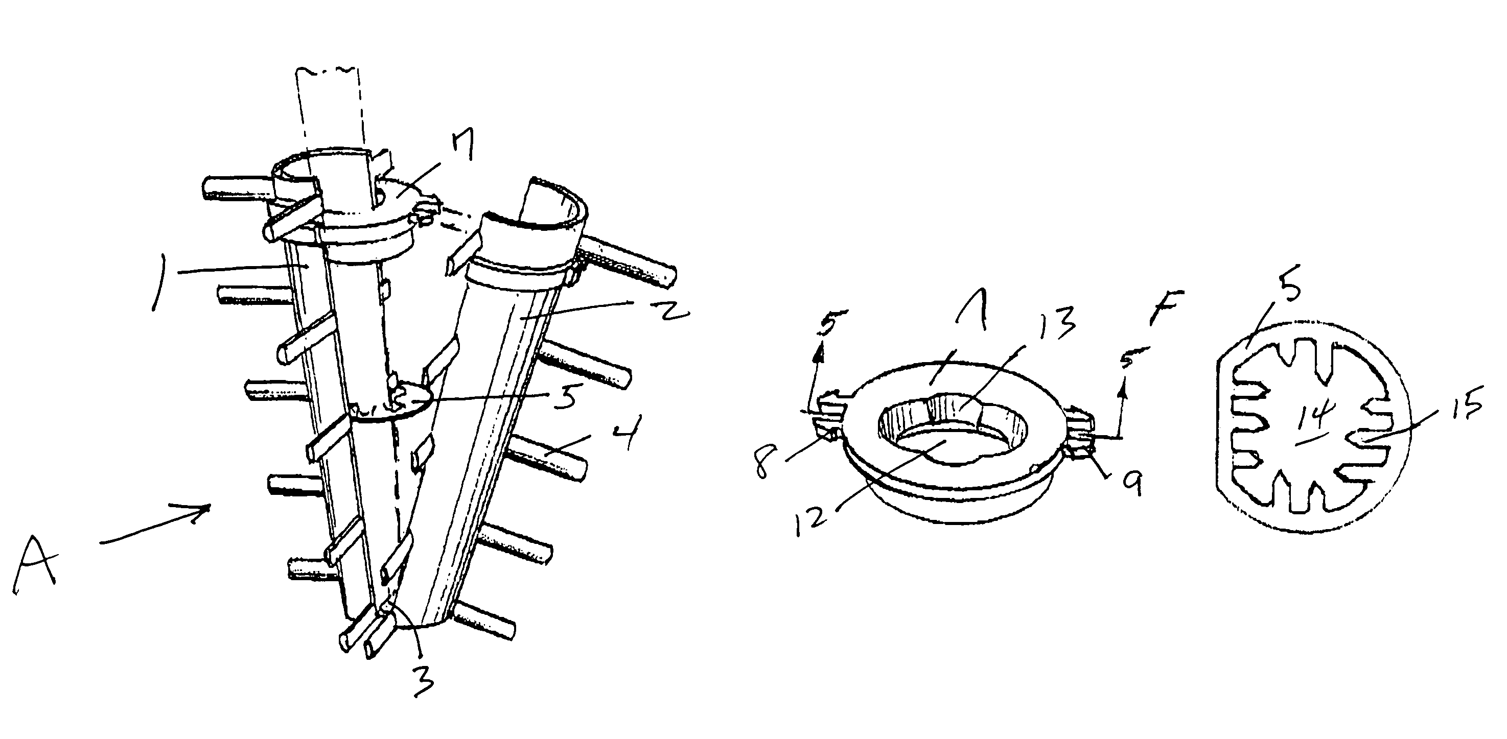
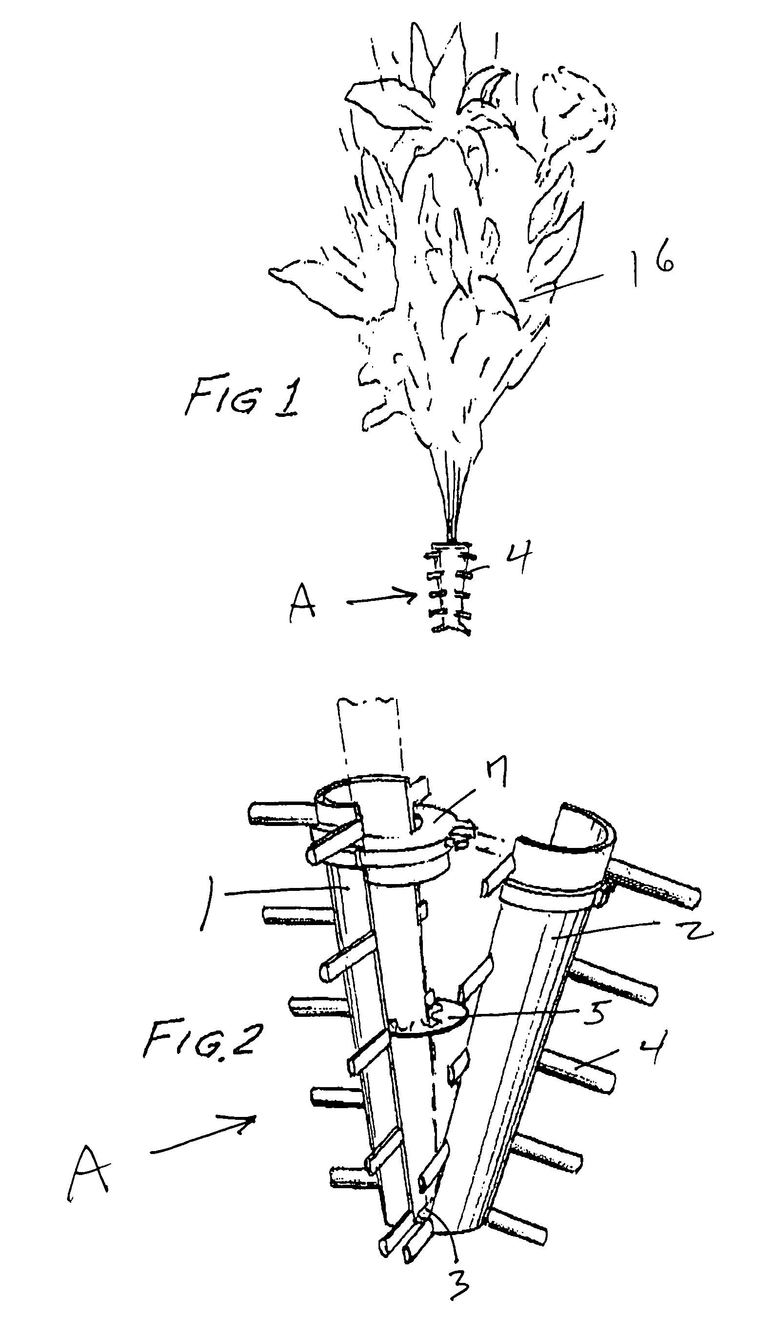
[0013]With reference to the drawings and with particular reference to FIG. 1, the basic structure of the flower holder is shown and includes a pair of generally semicircular base elements 1 and 2 which are foldably joined at connecting joint 3 and combine to form the holder generally identified by the letter A. Multiple flexible laterally projecting extensions 4 extend outwardly from each of the base elements 1 and 2.

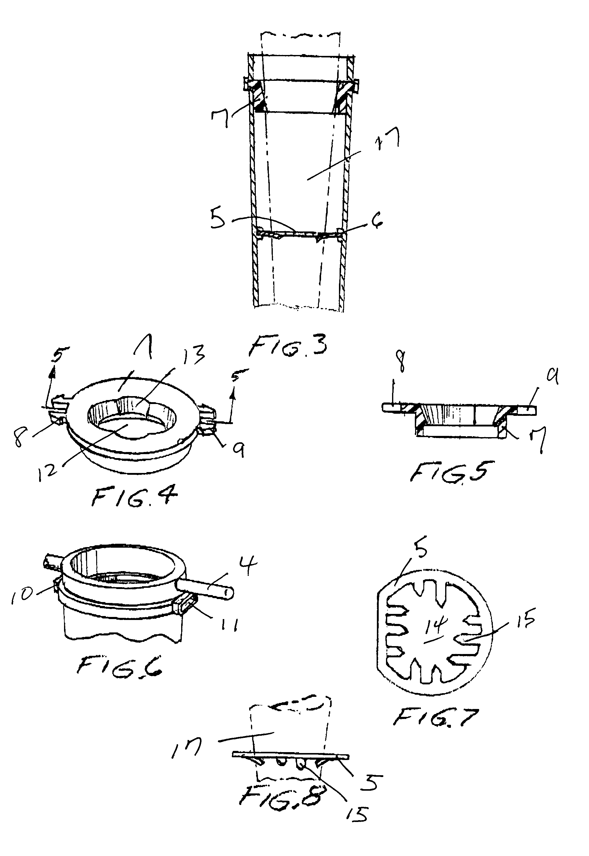
[0014]According to this invention, lower disc 5 is provided and is adapted to be positioned in groove 6 formed on the inner surface of base elements 1 and 2 and is positioned approximately in the middle between the top and bottom of holder A. Also, according to this invention, upper disc 7 is adapted to be secured to the upper portion of holder A by means of a pair of flexible fasteners 8 and 9 which are insertable into locking apertures 10 and 11, respectively.

[0015]As best shown in FIG. 4, upper disc 7 includes aperture 12 formed therein. Formed in upper disc 7 and ar...


PUM


Abstract

A holder for silk flowers including multiple extensions extending laterally outwardly of the holder, a pair of spaced discs respectively interconnected with the inner surface of the holder, a pair of apertures formed respectively in the discs, and multiple pointed prongs extending from the lower disc and into the aperture formed therein.

Description

[0001]The benefits under 35 U.S.C. 119 are claimed of provisional patent application 60 / 658,466 filed Mar. 7, 2005.BACKGROUND OF THE INVENTION[0002]This invention relates to cemetery flower holders. Generally, cemetery flowers are displayed in a brass or similar type vessel which is affixed to a gravesite memorial. Typically, silk flowers are inserted into a cone-shaped foam insert which is then placed into the flower vessel. If the foam insert is too large, it must be reduced in size by carving away the excess material. If the holder is too small, the entire flower assembly is prone to be blown away by high winds or it simply floats upwardly when the flower container fills with water.SUMMARY OF THE INVENTION[0003]A holder for silk flowers having multiple extensions extending outwardly therefrom, at least one disc positioned in a groove formed on the interior of the holder, an aperture formed in the disc, and at least one prong projecting from the disc and into the aperture.BRIEF DE...

Claims


Application Information

Patent Timeline
Patent Type & Authority Patents(United States)
IPC IPC(8): A47G7/00A47G7/07
CPCA47G7/02
Inventor BROEL, DAVID J.BROEL, RUBY E.
Owner D R BROEL
Learn More