
Anti-rotation device for a steerable rotary drilling device

a rotary drilling and anti-rotation technology, which is applied in the direction of drilling pipes, drilling rods, directional drilling, etc., can solve the problems of reduced drilling bit penetration rate, frequent problems, and wear of downhole motors, and achieve the effect of facilitating the operation of the drilling direction control device and simplifying drilling operations

Inactive Publication Date: 2007-12-11
HALLIBURTON ENERGY SERVICES INC
View PDF52 Cites 26 Cited by
  • Summary
  • Abstract
  • Description
  • Claims
  • Application Information

AI Technical Summary

Benefits of technology

[0040]The distal radial bearing may be comprised of any bearing, bushing or similar device which is capable of radially and rotatably supporting the drilling shaft while transmitting the effects of deflection of the drilling shaft past the distal radial bearing. For example, the distal radial bearing may allow for radial displacement of the drilling shaft. Preferably, however, the distal radial bearing is comprised of a fulcrum bearing which facilitates pivoting of the drilling shaft at the distal radial bearing location.
[0144]The orienting step may be comprised of communicating the desired orientation of the drilling string directly from the surface of the wellbore to the drilling direction control device either with or without manipulating the drilling string. Preferably, however, the orienting step is comprised of comparing a current orientation of the drilling string with the desired orientation of the drilling string and rotating the drilling string to eliminate any discrepancy between the current orientation and the desired orientation. Once the desired orientation of the drilling string is achieved by manipulation of the drilling string, the desired orientation may then be communicated to the drilling direction control device either directly from the surface of the wellbore or from a drilling string orientation sensor located somewhere on the drilling string.

Problems solved by technology

However, various problems are often encountered with sliding drilling.
As well, the downhole motor tends to be subject to wear given the traditional, elastomer motor power section.
Furthermore, since the drilling string is not rotated during sliding drilling, it is prone to sticking in the wellbore, particularly as the angle of deflection of the wellbore from the vertical increases, resulting in reduced rates of penetration of the drilling bit.
Other traditional problems related to sliding drilling include stick-slip, whirling, differential sticking and drag problems.
For these reasons, and due to the relatively high cost of sliding drilling, this technique is not typically used in directional drilling except where a change in direction is to be effected.
However, rotary drilling tends to provide relatively limited control over the direction or orientation of the resulting wellbore as compared to sliding drilling, particularly in extended-reach wells.
Although the use of a combination of sliding and rotary drilling may permit satisfactory control over the direction of the wellbore, the problems and disadvantages associated with sliding drilling are still encountered.
However, none of these attempts have provided a fully satisfactory solution.
As a result, it has been found that the drilling string may be exposed to excessive bending stress.
However, it has been found that the use of a flexible or articulated shaft to avoid the generation of excessive bending force on the drilling string may not be preferred.
Specifically, it has been found that the articulations of the flexible or articulated shaft may be prone to failure.

Method used


Image

  • Anti-rotation device for a steerable rotary drilling device
  • Anti-rotation device for a steerable rotary drilling device
  • Anti-rotation device for a steerable rotary drilling device

Examples


Embodiment Construction

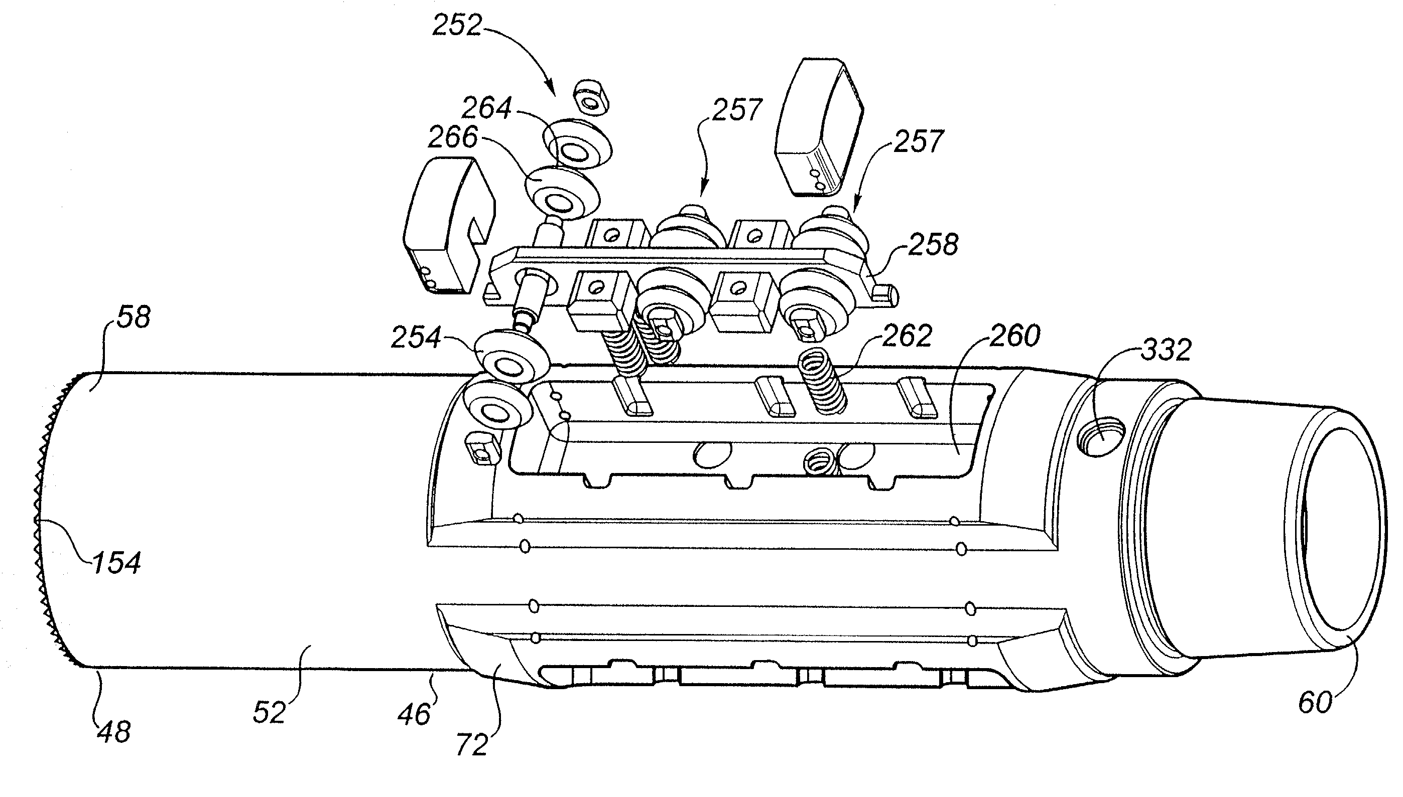
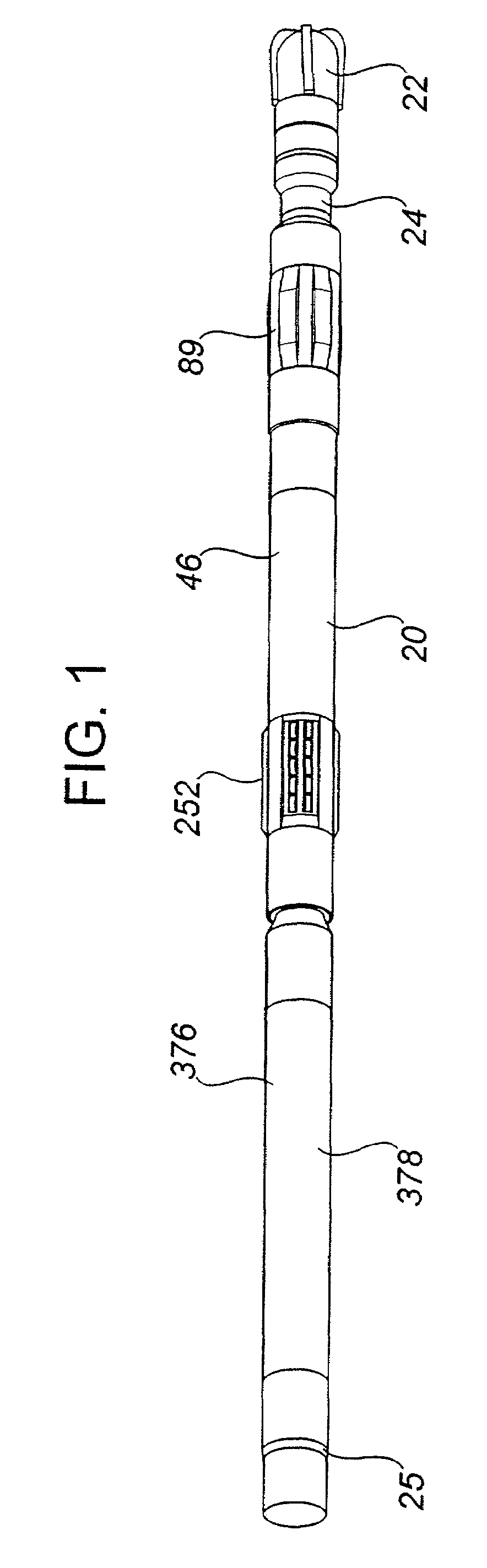
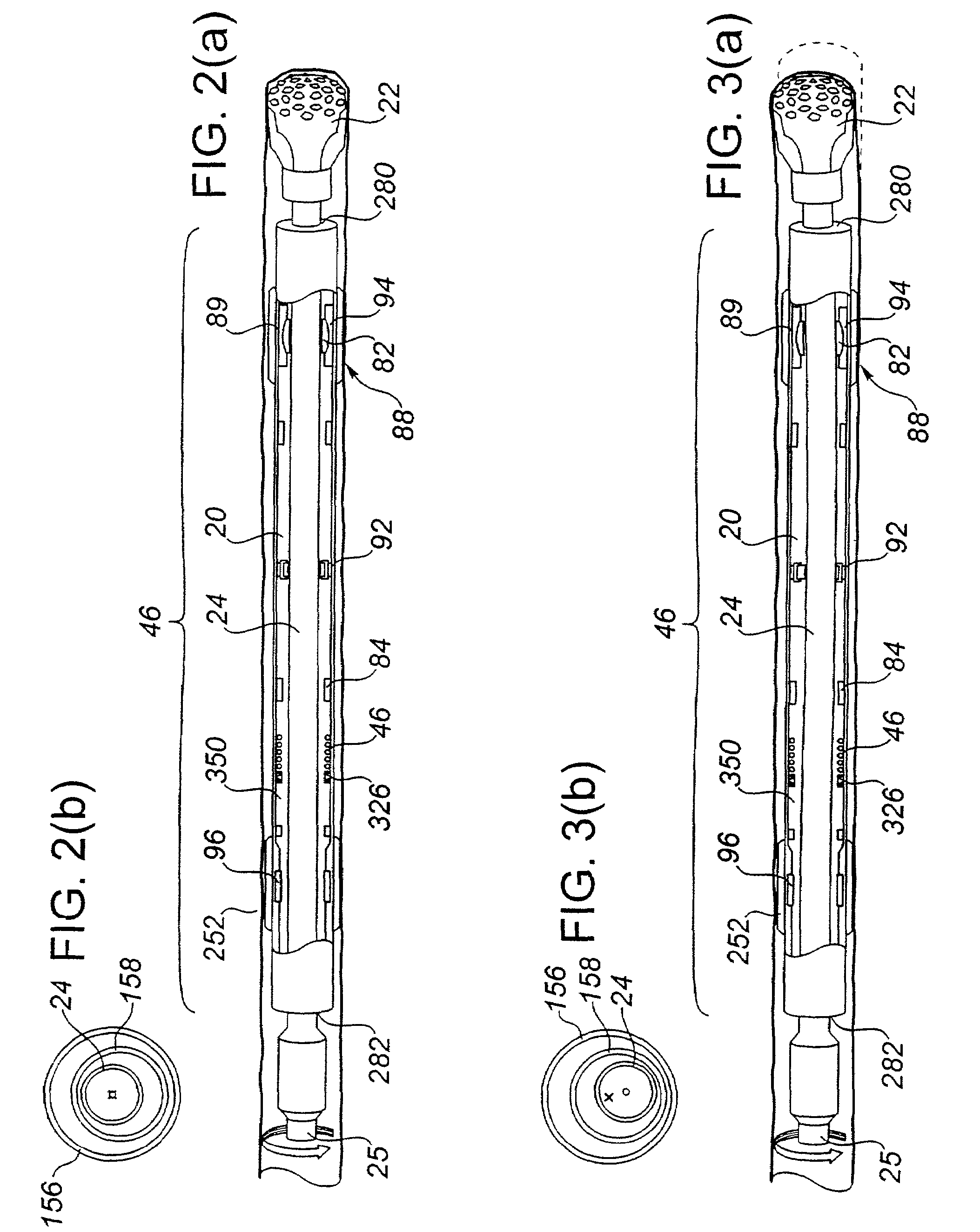
[0189]The within invention is comprised of a drilling direction control device (20) and a method for using the device (20). The device (20) permits directional control over a drilling bit (22) connected with the device (20) during rotary drilling operations by controlling the orientation of the drilling bit (22). As a result, the direction of the resulting wellbore may be controlled. Specifically, in the preferred embodiment, the device (20) and method of the within invention maintain the desired orientation of the drilling bit (22) by maintaining the desired toolface of the drilling bit (22) and the desired bit tilt angle, while preferably enhancing the rotations per minute and rate of penetration.

[0190]The drilling direction control device (20) is comprised of a rotatable drilling shaft (24) which is connectable or attachable to a rotary drilling string (25) during the drilling operation. More particularly, the drilling shaft (24) has a proximal end (26) and a distal end (28). The...


PUM


Abstract

In a drilling apparatus of the type comprising a rotatable drilling shaft and a housing for rotatably supporting a length of the drilling shaft for rotation therein, a rotation restraining device associated with the housing for restraining rotation of the housing. In one embodiment, the rotation restraining device is comprised of at least one roller on the housing, the roller having an axis of rotation substantially perpendicular to a longitudinal axis of the housing and being oriented such that it is capable of rolling about its axis of rotation in response to a force exerted on the roller substantially in the direction of the longitudinal axis of the housing. In a further embodiment, the rotation restraining device is comprised of at least one piston on the housing.

Description

FIELD OF INVENTION[0001]The present invention relates to a steerable rotary drilling device and a method for directional drilling using a rotary drilling string. Further, the present invention relates to a drilling direction control device and a method for controlling the direction of rotary drilling. As well, the invention relates to a rotation restraining device or an anti-rotation device for use with a steerable rotary drilling device or a drilling direction control device.BACKGROUND OF INVENTION[0002]Directional drilling involves varying or controlling the direction of a wellbore as it is being drilled. Usually the goal of directional drilling is to reach or maintain a position within a target subterranean destination or formation with the drilling string. For instance, the drilling direction may be controlled to direct the wellbore towards a desired target destination, to control the wellbore horizontally to maintain it within a desired payzone or to correct for unwanted or und...

Claims


Application Information

Patent Timeline
Patent Type & Authority Patents(United States)
IPC IPC(8): E21B17/10E21B7/06
CPCE21B7/062E21B17/1057E21B7/067
Inventor CARGILL, EDWARD JAMESRESTAU, BRYAN JAMES
Owner HALLIBURTON ENERGY SERVICES INC
Learn More