
System and method for compressing the dynamic range of an image

a dynamic range and image technology, applied in the field of computer image processing, can solve the problems of generating other artifacts, reducing the dynamic range of images, and affecting the quality of images, so as to reduce the effect of relatively high gradients, and reduce the effect of large global differences

Active Publication Date: 2007-12-04
YISSUM RES DEV CO OF THE HEBREWUNIVERSITY OF JERUSALEM LTD
View PDF5 Cites 37 Cited by
  • Summary
  • Abstract
  • Description
  • Claims
  • Application Information

AI Technical Summary

Benefits of technology

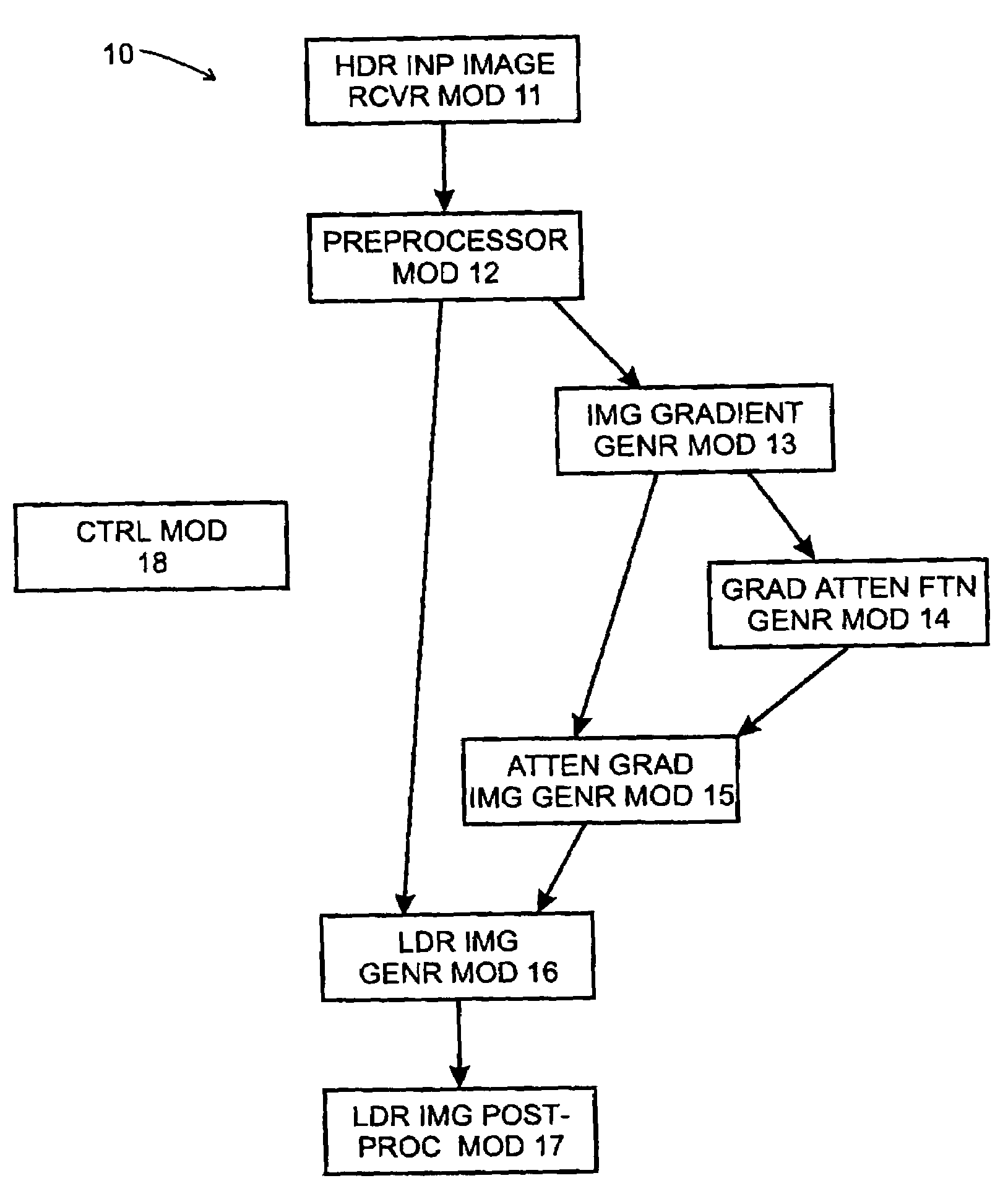
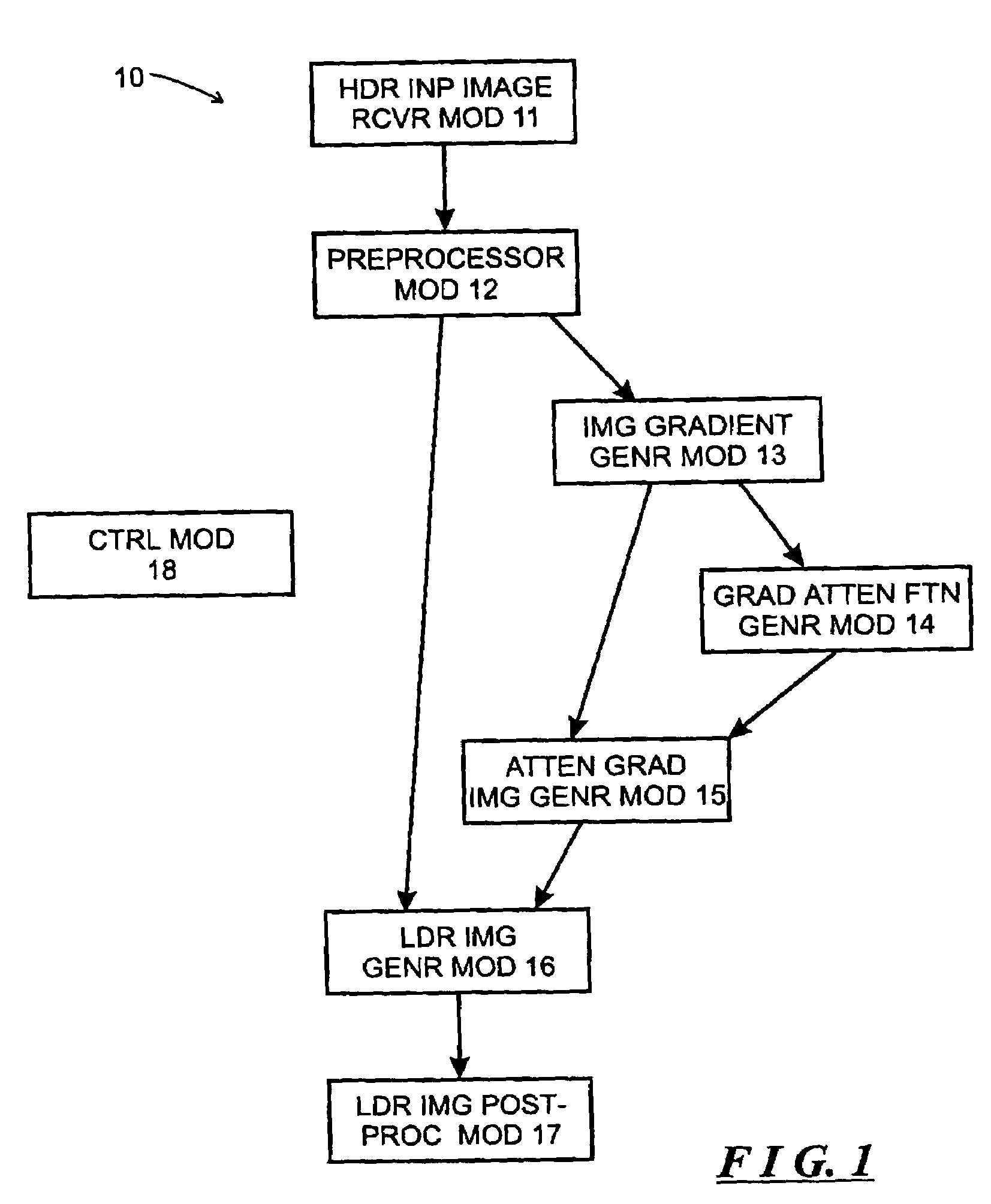
[0013]Generally, the invention makes use of the observation that the human visual system is not as sensitive to the absolute luminances reaching the eye, as to local changes in the ratios of the intensities, and further that the human visual system reduces the effect of large global differences, which may be associated with differences in illumination over the scene. The invention further makes use of the observation that drastic changes in the luminance of an image gives rise to gradients in the luminance of large magnitudes at some scale. On the other hand, fine details, such as textures, have luminances with much lower gradients. In accordance with those observations, a system in accordance with invention identifies large gradients at various scales, and attenuates their magnitudes, while leaving the directions of the gradients unchanged. The attenuation is progressive, so as to reduce relatively high gradients more than somewhat lower gradients. On the other hand, a system in accordance with the invention preserves fine details by increasing relatively low gradients, also in a progressive manner. The result is to compress the gradients. Such a system converts the compressed gradients into an image whose luminance has a lower dynamic range (an LDR image) relative to the dynamic range of the luminance of the original image.

Problems solved by technology

A problem arises with such HDR images, since conventional computer video display or other output devices, such as monitors, printers, and the like have a much lower dynamic range than the HDR images.
Linear scaling is relatively simple to carry out, and it preserves relative contrasts in a perfect fashion, but a severe loss of visibility of elements of the image can occur, particularly if the output device's dynamic range is significantly lower than the dynamic range of the image.
Problems arise in the spatially invariant mapping methodologies as described above, since separating the image I into the reflectance R and illumination L components is an ill posed problem.
Various methodologies have been proposed to vary the methodology to eliminate the halo effects, but many of them are computationally intensive, or they do not totally eliminate the haloing, or they may result in other artifacts being generated.

Method used


Image

  • System and method for compressing the dynamic range of an image
  • System and method for compressing the dynamic range of an image
  • System and method for compressing the dynamic range of an image

Examples


Embodiment Construction

[0019]FIG. 1 is a functional block diagram of a gradient domain high-dynamic-range (“HDR”) compression system 10 constructed in accordance with the invention. The gradient domain HDR compression system 10 receives a HDR image and generates therefrom a low-dynamic-range (“LDR”) image that can be accommodated by an output device such as, for example, a video display, a printer or other output device.

[0020]The gradient domain HDR compression system 10 is designed with reference to two general observations. First, the human visual system is not as sensitive to the absolute luminances reaching the eye, as to local changes in the ratios of the intensities, and further that the human visual system reduces the effect of large global differences, which may be associated with differences in illumination over the scene. In addition, drastic changes in the luminance of an image gives rise to gradients in the luminance of large magnitudes at some scale. On the other hand, fine details, such as t...


PUM


Abstract

A gradient domain compression system generates, from an input image having a high luminance dynamic range, an output image having a lower luminance dynamic range. The system comprises a gradient image generator module, a gradient compression module, and an output image generator module. The gradient image generator module is configured to generate, from the input image, a gradient image representing, for respective points of the input image, gradient values in the luminance of the input image. The gradient compression module is configured to receive the gradient image and generate a compressed range gradient image in which the range of gradient values are compressed. The output image generator module is configured to receive the compressed range gradient image and to generate therefrom an image, the image generated by the output image generator module comprising the output image.

Description

FIELD OF THE INVENTION[0001]The invention relates generally to the field of computer image processing, and more particularly to systems and methods for compressing the dynamic range of an image.BACKGROUND OF THE INVENTION[0002]High dynamic range (“HDR”) images are becoming increasingly common in a number of applications. A HDR image of a scene can be generated by conventional computer graphics techniques. A HDR image of a scene can also be constructed from a series of photographs taken by an image capture device of the scene at different shutter speeds or under different lighting conditions. Typically, the various photographs taken at different shutter speeds, for example, will reveal different details of the objects in the scene. Using one or more of several known techniques, the photographs can be combined to provide a single image that can contain details of the various objects in the scene that may be visible in one or more, but not necessarily all, of the photographs, and which...

Claims


Application Information

Patent Timeline
Patent Type & Authority Patents(United States)
IPC IPC(8): G06K9/40G06K9/00G06T5/40G06T5/50G06T9/00H04N7/26
CPCG06T5/009G06T5/40G06T5/50H04N19/33H04N19/172H04N19/117H04N19/14H04N1/4072
Inventor FATTAL, RAANANLISCHINSKI, DANIELWERMAN, MICHAEL
Owner YISSUM RES DEV CO OF THE HEBREWUNIVERSITY OF JERUSALEM LTD
Learn More