Electrostatic motor including projections providing a clearance between stator and slider electrode members

a technology of slider electrode and stator electrode, which is applied in the direction of electrostatic motor, electrostatic generator/motor, electrical apparatus, etc., can solve the problems of difficult to make beads etc. enter into this clearance, difficult to maintain insulation, and electrical leakage, so as to prolong the service life of stator electrode member and slider electrode member

Inactive Publication Date: 2007-12-04
FANUC LTD
View PDF13 Cites 9 Cited by
  • Summary
  • Abstract
  • Description
  • Claims
  • Application Information

AI Technical Summary

Benefits of technology

[0011]Accordingly, an object of the present invention is to provide an electrostatic motor which can prolong the service life of the stator electrode member and the slider electrode member.
[0018]According to the present invention, a plurality of projections are provided at one or both of the contacting surfaces of the stator electrode member and the slider electrode member. By the contact of the projections of one surface with the contacting surface or projections of the other surface, the clearance between the stator electrode member and the slider electrode member is maintained and therefore the service life of the stator electrode member and the slider electrode member can be prolonged.

Problems solved by technology

However, if there is gas present between the drive electrode patterns of the stator electrode member and the drive electrode patterns of the slider electrode member, a corona discharge etc. will be generated, so it will become difficult to maintain the insulation.
However, the clearance between the stator electrode member and the slider electrode member is a very narrow clearance of about tens of micrometers, therefore, it is difficult to make the beads etc. enter into this clearance again.
Further, over the long term, the stator electrode member and the slider electrode member are damaged by the friction resulting in electrical leakage, short-circuits and thereby reducing the service life.

Method used


Image

  • Electrostatic motor including projections providing a clearance between stator and slider electrode members
  • Electrostatic motor including projections providing a clearance between stator and slider electrode members
  • Electrostatic motor including projections providing a clearance between stator and slider electrode members

Examples


first embodiment

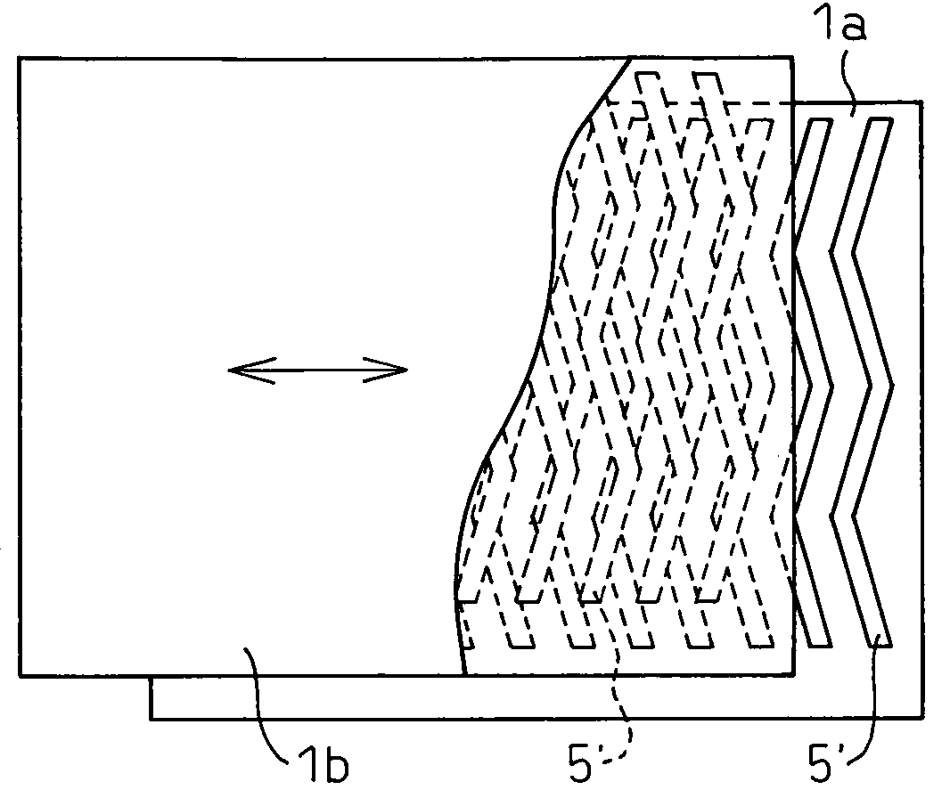
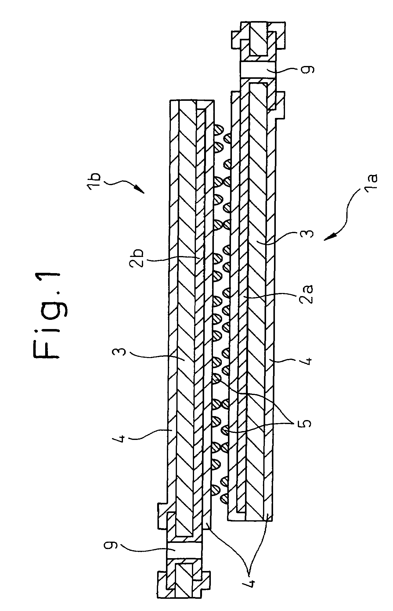
[0034]FIG. 1 is a sectional view of principal parts of an electrostatic motor built up of a set of a stator electrode member 1a and a slider electrode member 1b according to the present invention.

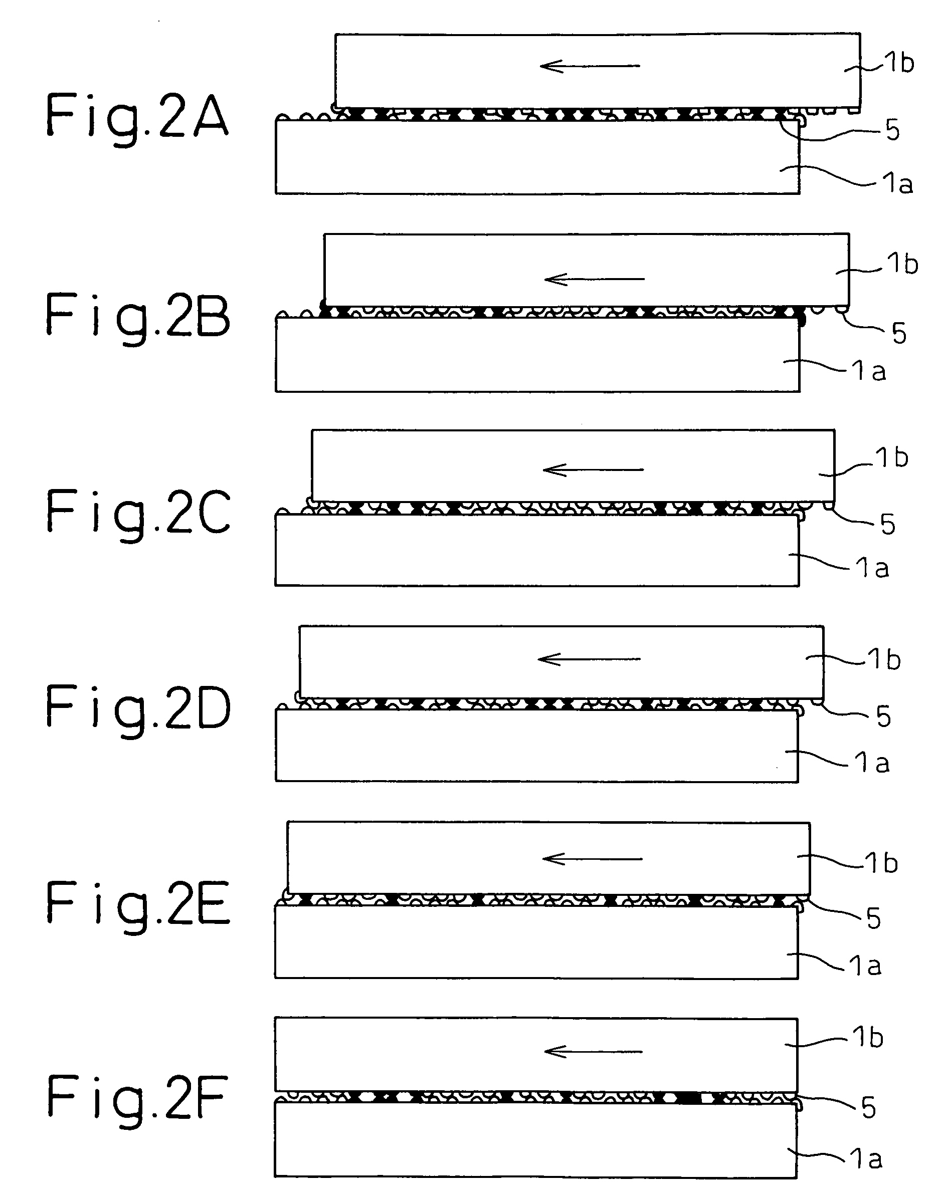
[0035]The stator electrode member 1a and slider electrode member 1b of the electrostatic motor according to the first embodiment is different from the conventional stator electrode member and slider electrode member in that convex projections 5 are fixed to facing surfaces of the stator electrode member 1a and the slider electrode member 1b of the electrostatic motor according to the first embodiment of the present invention. The rest of the configuration is the same as that of the conventional stator electrode member and slider electrode member described with reference to FIG. 12 and FIGS. 13A to 13D. The projections 5 provided on the facing surfaces of these stator electrode member 1a and slider electrode member 1b contact each other to thereby maintain a clearance between the stator elec...

second embodiment

[0040]FIG. 3 is a sectional view of principal parts of an electrostatic motor built up of a set of a stator electrode member 1a and a slider electrode member 1b according to the present invention.

[0041]In the electrostatic motor according to the second embodiment, the projections 5 and the cover films 4 (plastic films) are integrally formed. The cover films 4 are formed so that projections 5 forming parts of spherical members or elliptical members, etc., are formed on the surfaces of the cover films 4. The cover films 4 are attached by a binder to the drive electrode side surfaces of the base films 3 provided with the stator drive electrode patterns 2a and the slider drive electrode patterns 2b, so that they cover the stator drive electrode patterns 2a or the slider drive electrode patterns 2b. The stator electrode member 1a and the slider electrode member 1b are produced in this way. The stator electrode member 1a and the slider electrode member 1b produced in this way are arranged...

third embodiment

[0042]FIG. 4 is a sectional view of principal parts of an electrostatic motor built up of a set of a stator electrode member 1a and a slider electrode member 1b according to the present invention.

[0043]In the third embodiment, use is made of a stator electrode member 1a or a slider electrode member 1b formed by supporting members for forming the drive electrode patterns 2a or 2b in the air and in that state molding an insulating material 6 around them. The mold used for such a molding process is provided with shapes corresponding to the projections 5 of the molded article so that the projections 5 are integrally formed with the electrode member. If using insulative support members for supporting the members for forming the stator drive electrode patterns 2a or the slider drive electrode patterns 2b during the molding process, the insulative support members are preferably formed from a material of the same type as the insulating material to be molded so that the insulative support me...


PUM


Abstract

An electrostatic motor includes a stator electrode member (1a) and a slider electrode member (1b). The stator electrode member (1a) and the slider electrode member (1b) are provided with drive electrode patterns (2), and the drive electrode patterns are covered by cover films (4). Surfaces of the stator electrode member (1a) and the slider electrode member (1b) contacting each other are provided with a plurality of minute projections (5). A clearance between the stator electrode member and the slider electrode member is maintained by the contact of the projections. The projections (5) may also be provided on only one of the stator electrode member (1a) and the slider electrode member (1b), with the other electrode member having a flat surface.

Description

BACKGROUND OF THE INVENTION[0001]1. Field of the Invention[0002]The present invention relates to an electrostatic motor driven by electrostatic force.[0003]2. Description of the Related Art[0004]An electrostatic motor includes a stator electrode member and a slider electrode member, which are provided with drive electrode patterns comprised of a plurality of conductors arranged at a fine pitch. An electrostatic motor is driven by applying cyclic voltage to these drive electrode patterns and utilizing the electrostatic attraction force between different polar electrodes and the electrostatic repulsion force between same polar electrodes between the stator electrode member and the slider electrode member, thereby causing the slider electrode member to slide relative to the stator electrode member.[0005]Such an electrostatic motor includes a linear type and a rotary type. In a linear electrostatic motor, the slider electrode member is made to relatively slide linearly with respect to t...

Claims


Application Information

Patent Timeline
Patent Type & Authority Patents(United States)
IPC IPC(8): H02N1/00
CPCH02N1/004
Inventor ODAKA, SHUNICHIKARIYA, ISAO
Owner FANUC LTD
Why Eureka
Try Eureka