
Sensor system

a sensor and sensor technology, applied in the field of sensor systems, can solve the problems of unsatisfactory effect, unsatisfactory effect, and inconvenient maintenance of the system, and achieve the effect of effective and inexpensiv

Inactive Publication Date: 2007-11-27
BAE SYSTEMS PLC
View PDF15 Cites 30 Cited by
  • Summary
  • Abstract
  • Description
  • Claims
  • Application Information

AI Technical Summary

Benefits of technology

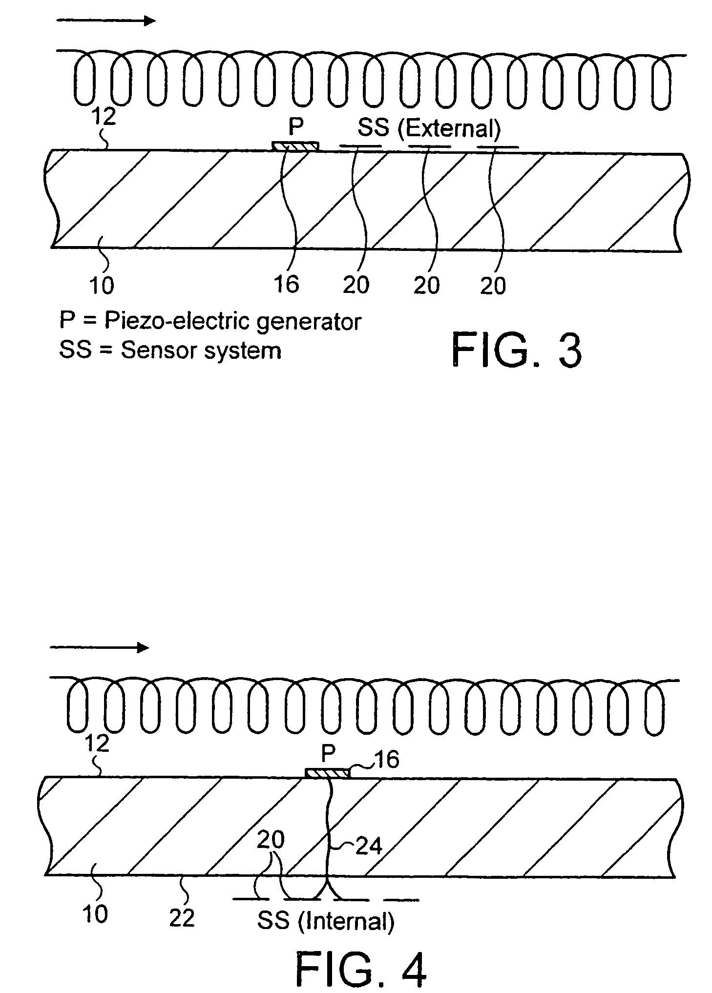
[0004]A further aim of the invention is to provide an effective and inexpensive sensor system having local power generators arranged to exploit the environmental characteristics at each sensing location for providing the small amounts of electrical power required.
[0022]Advantageously, the sensor system also includes means for communicating with a remote control unit, for example employing electromagnetic radiation. Such communication means may conveniently comprise short range wireless data links.

Problems solved by technology

Such sensor systems are complicated and expensive to install, in view of the need for complex wiring systems for supplying power to the sensors and for transmitting sensor information to the control unit from the sensors.
Moreover, such systems are costly to maintain, in view of the need to monitor the integrity of the individual wired connections and / or to build in sufficient redundancy to allow for the failure of such connections without impairing the overall functioning of the system.
Such systems furthermore require a substantial central power source, which may be costly to provide and may result in undesirable bulk in an environment where weight and space savings are at a premium.

Method used


Image

  • Sensor system
  • Sensor system
  • Sensor system

Examples


Embodiment Construction

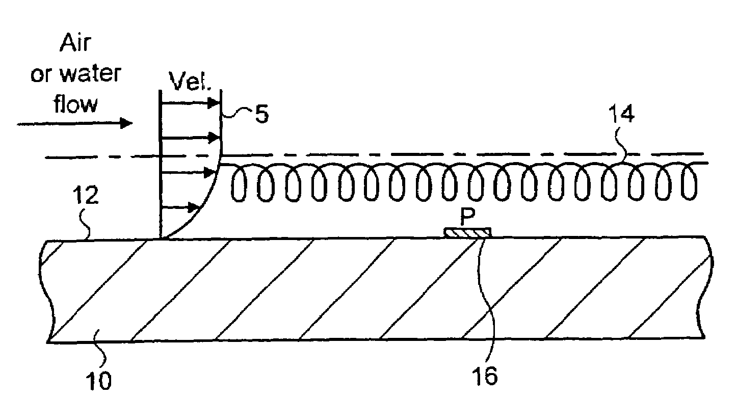
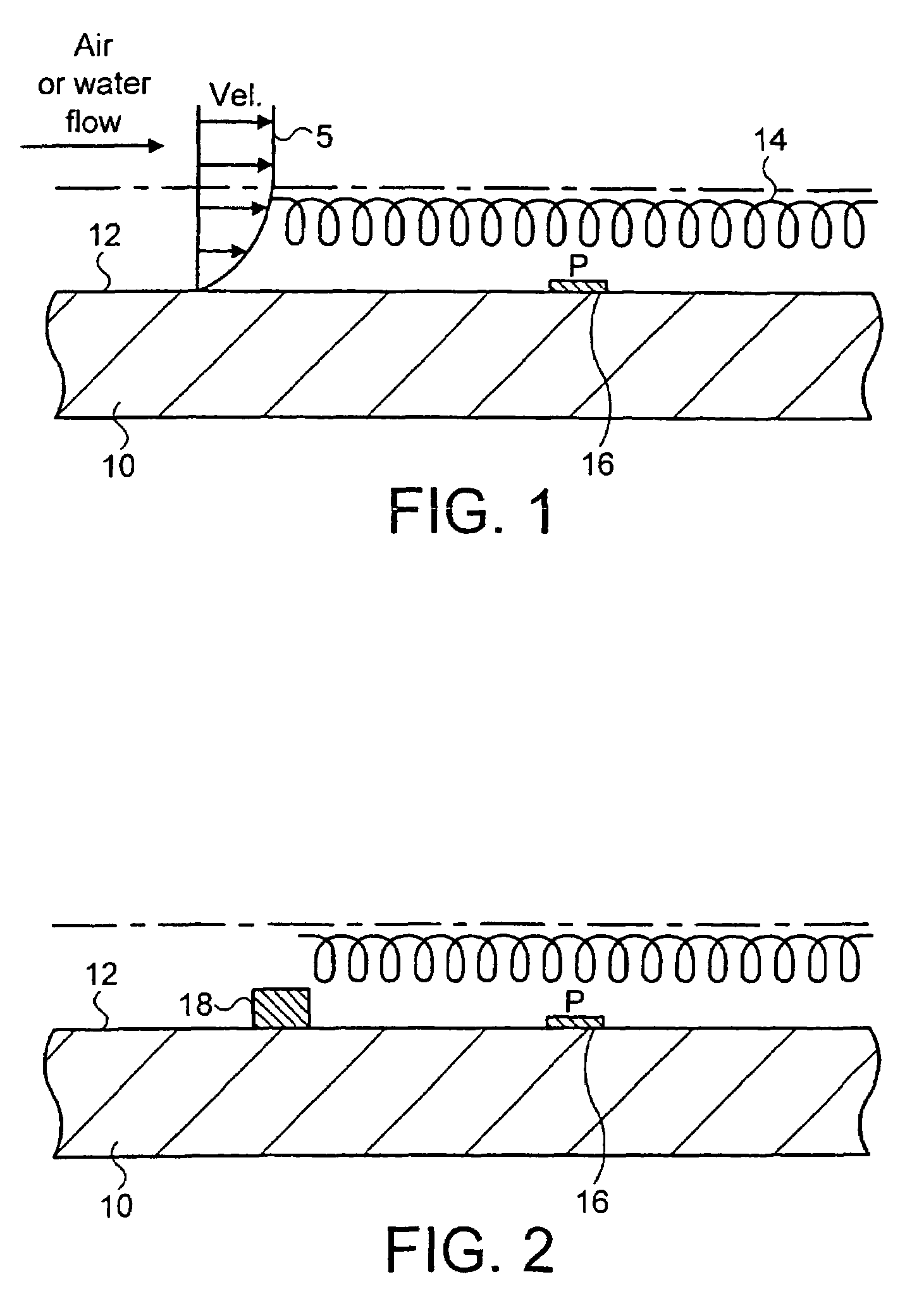
[0037]Referring initially to FIG. 1, a local power generator for use in the sensor system of the invention will first be described. As shown in FIG. 1, a panel 10 of a vehicle, such as an aircraft, has an external surface 12 which is subject to a flow of fluid thereover in use due to the movement of the vehicle. For example, the panel 10 may comprise the skin of an aircraft wing, which is subject to a flow of air during manoeuvring on the ground, take off, flight and landing. As is well known, fluid flow past the panel 10 in these conditions will generate a boundary layer 14 of turbulence adjacent the panel 10 as illustrated.

[0038]Mounted on the surface 12, or alternatively embedded within the panel 10 so as to be proximate to or flush with the surface 12, is a solid state transducer 16, which in the present instance is a piezo-electric device. This piezo-electric device 16 is subject in use to the turbulence of the air in the boundary layer 14 and is arranged to be responsive to su...


PUM


Abstract

The invention provides apparatus having a sensor system for providing sensor information for a monitoring, control or other operating function of the apparatus. The sensor system comprises: a transducer (16) adapted to be responsive to a predetermined environmental characteristic of the apparatus for providing an electrical output, and means (18) adjacent to the transducer to accentuate the said characteristic. At least one sensor (20) is arranged to be operated by power derived from the electrical output for generating a detection signal, and means (38, 40) arranged to be operated by power derived from the electrical output and responsive to the detection signal are also provided for communicating sensor information to a processing unit remote from the sensor system and associated with the said function.

Description

[0001]This invention concerns a sensor system for providing sensor information for a monitoring, control or other operating function of an apparatus, in particular a land, sea or air vehicle.BACKGROUND OF THE INVENTION[0002]It is well known in vehicles such as ships and aircraft to employ a plurality of sensors connected together and to a remote central control unit by means of wired connections for supplying sensor information for a monitoring, control or other operational function of the vehicle. Such sensor systems are complicated and expensive to install, in view of the need for complex wiring systems for supplying power to the sensors and for transmitting sensor information to the control unit from the sensors. Moreover, such systems are costly to maintain, in view of the need to monitor the integrity of the individual wired connections and / or to build in sufficient redundancy to allow for the failure of such connections without impairing the overall functioning of the system. ...

Claims


Application Information

Patent Timeline
Patent Type & Authority Patents(United States)
IPC IPC(8): G08B1/08G01D21/00G01D1/18G01D5/39G01D21/02H02N2/00
CPCG01D5/39G01D1/18
Inventor SEYFANG, GEORGE REGINALDSALKELD, GEOFFREYHUNTER, CHRISTOPHER JOHNCALDER, NEIL JOHN
Owner BAE SYSTEMS PLC
Learn More