
Peristaltic pump

a pump and peristaltic technology, applied in the direction of positive displacement liquid engines, rotary piston liquid engines, printing, etc., can solve the problems of inconsistent fluid pumping and permanent set in the tub

Active Publication Date: 2007-11-27
HEWLETT PACKARD DEV CO LP
View PDF25 Cites 74 Cited by
  • Summary
  • Abstract
  • Description
  • Claims
  • Application Information

AI Technical Summary

Benefits of technology

The present invention relates to a peristaltic pump that is used in a fluid delivery system for printers. The invention aims to solve the problem of inconsistent pumping caused by a permanent set in the tube when the pump is not in use. The invention provides a pump with a plurality of rollers that can move to compress the tube and pump fluid in a consistent and efficient manner. The invention also includes a printer with a media supply, carriage, pens, ink supplies, and controller, which work together to deliver fluid to the printer. The invention provides a more reliable and consistent ink supply system for printers.

Problems solved by technology

This results in a permanent set in the tube and the inconsistent pumping of fluid.

Method used


Image

  • Peristaltic pump
  • Peristaltic pump
  • Peristaltic pump

Examples


Embodiment Construction

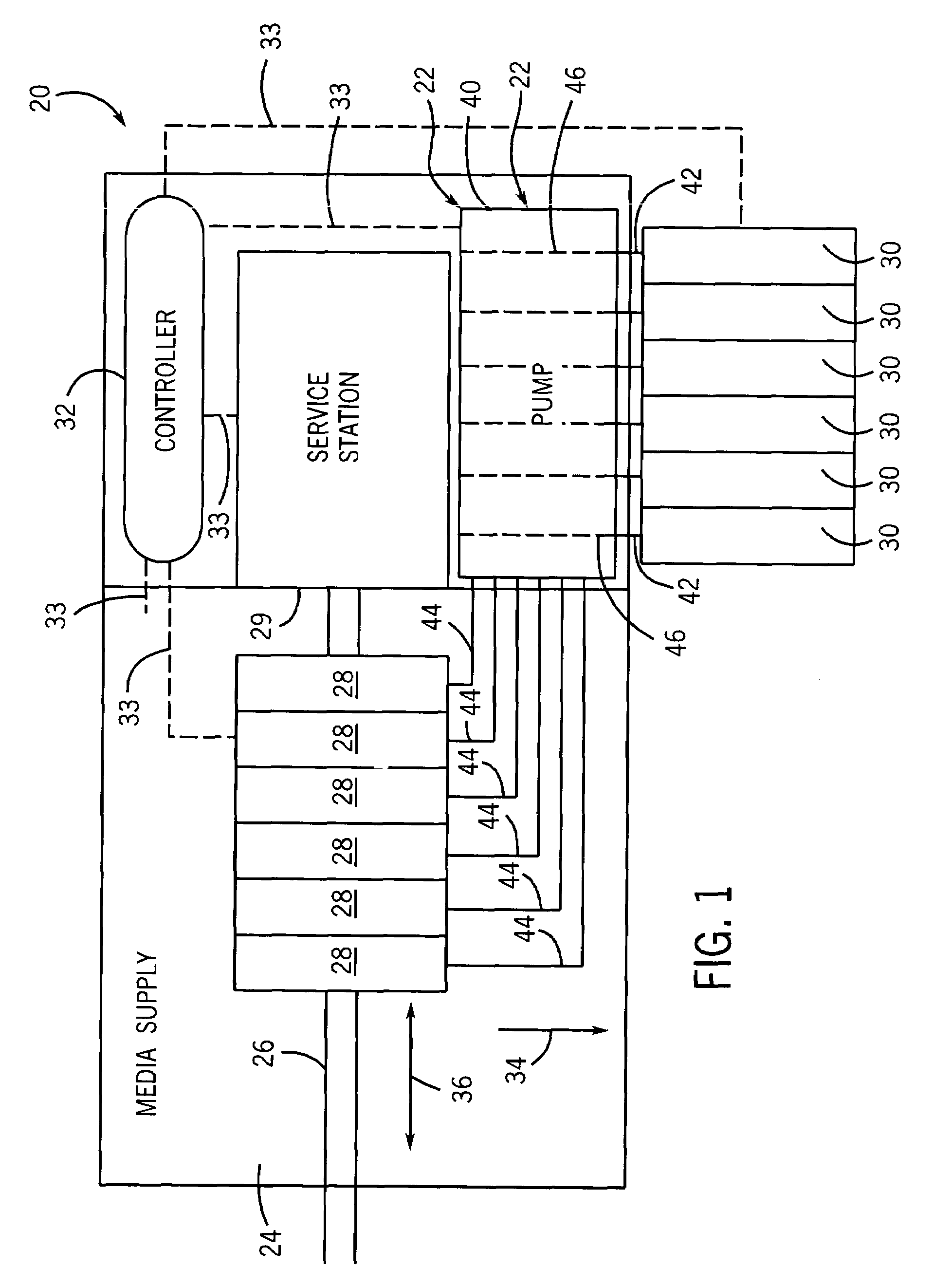
[0017]FIG. 1 schematically illustrates printer 20 utilizing one example of a fluid delivery system 22 of the present invention. In addition to fluid delivery system 22, printer 20 includes media supply 24, carriage 26, pens 28, ink supplies 30 and controller 32. Media supply 24 comprises a mechanism configured to supply and position media, such as paper, relative to carriage 26 and pens 28. Carriage 26 comprises a mechanism for moving pens 28 relative to the medium provided by media supply 24. In the particular embodiment illustrated, media supply 24 moves the medium relative to carriage 26 and pens 28 in the direction indicated by arrow 34 while carriage 26 moves pens 28 repeatedly across the medium in the directions indicated by arrow 36. Pens 28 (also known as print cartridges) comprise pens including printheads with nozzles for dispensing fluid ink upon the medium. Service station 29 is a conventionally known service station configured to service pens 28. Examples of servicing o...


PUM


Abstract

A peristaltic pump includes occluding surfaces rotatably supported by a support, an occlusion having an occlusion surface and a drive system configured to rotate occluding surfaces about a common axis. At least one of the support and the occlusion is movable towards the other of the support and the occlusion. The drive system is coupled to at least one of the support and the occlusion so as to move at least one of the support and the first occlusion.

Description

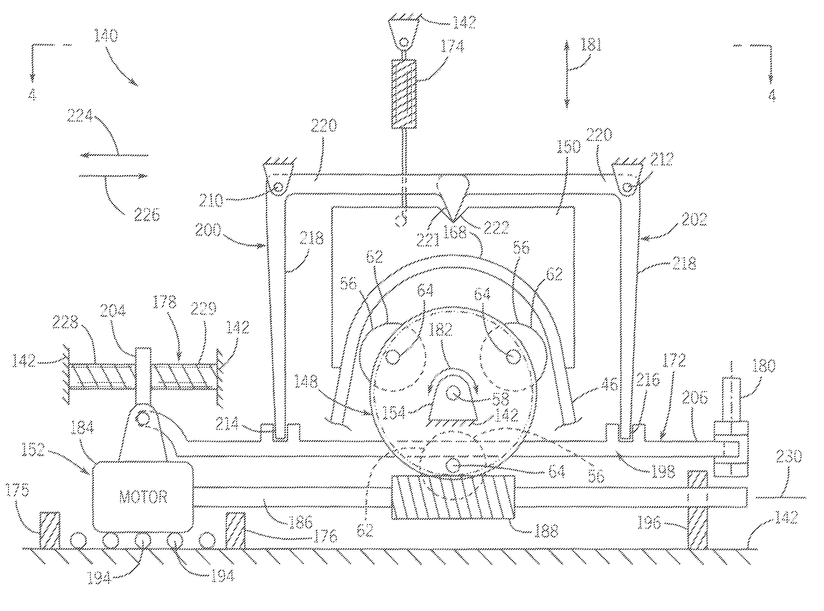
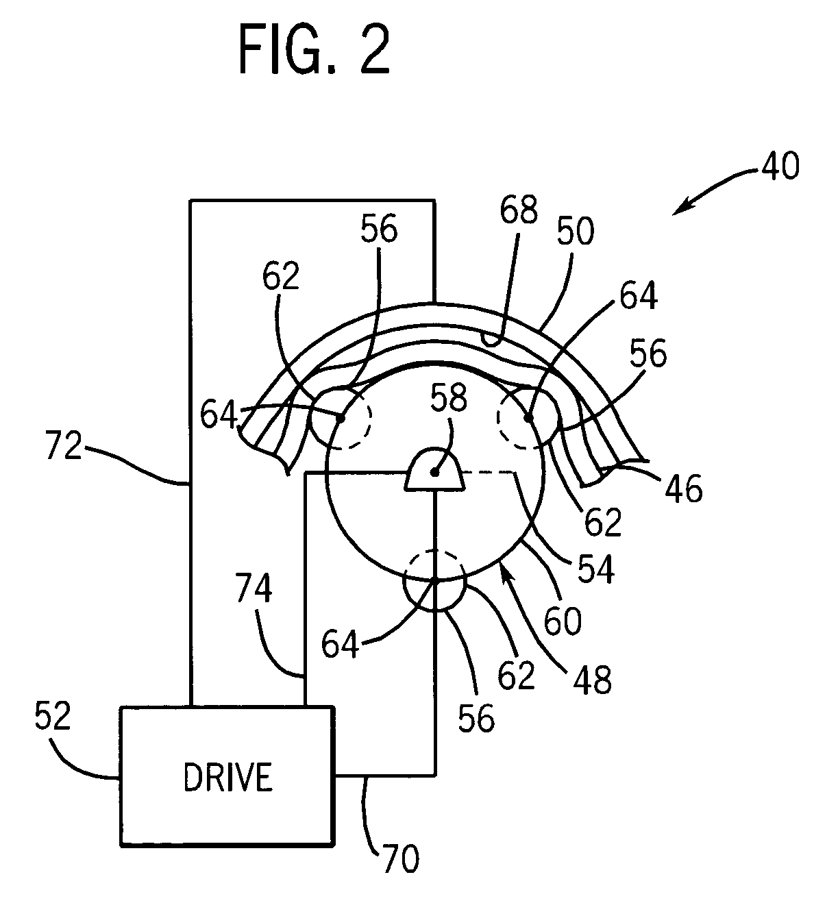
BACKGROUND OF THE INVENTION[0001]Peristaltic pumps are used in a wide variety of applications for pumping fluid. Peristaltic pumps typically include a roller assembly having a plurality of rollers which are rotated against a fluid-containing tube to successfully and progressively collapse or compress the tube against an occlusion to move fluid along the tube in the direction that the roller assembly is rotated. In many peristaltic pumps, the rollers are left in engagement with the tube when the pump is not in use. This results in a permanent set in the tube and the inconsistent pumping of fluid.BRIEF DESCRIPTION OF THE DRAWINGS[0002]FIG. 1 schematically illustrates a printer utilizing one example of a peristaltic pump of the present invention.[0003]FIG. 2 schematically illustrates the pump of FIG. 1 in greater detail.[0004]FIG. 3 is a front elevational view schematically illustrating a first alternative embodiment of the pump of FIG. 2 in a non-pumping state.[0005]FIG. 4 is a top pl...

Claims


Application Information

Patent Timeline
Patent Type & Authority Patents(United States)
IPC IPC(8): F04B43/12F04C5/00B41J2/175
CPCB41J2/17596F04B43/1284F04B43/1253
Inventor SOUZA, TIMOTHY M.
Owner HEWLETT PACKARD DEV CO LP
Learn More