
Methods and apparatus for illuminating environments

a technology of illumination and environment, applied in the field of illumination systems, can solve the problems of difficult and expensive transportation of neon, particular challenges and opportunities, and difficult and difficult neon light industry, and achieve the effect of facilitating information transportation and facilitating information transportation

Inactive Publication Date: 2007-11-27
SIGNIFY NORTH AMERICA CORP
View PDF369 Cites 193 Cited by
  • Summary
  • Abstract
  • Description
  • Claims
  • Application Information

AI Technical Summary

Benefits of technology

[0040]Unless otherwise indicated in a specific passage of this disclosure, the terms “processor” or “controller” are used herein interchangeably to describe various apparatus relating to the operation of one or more light sources. A processor or controller can be implemented in numerous ways, such as with dedicated hardware, using one or more microprocessors that are programmed using software (e.g., microcode) to perform the various functions discussed herein, or as a combination of dedicated hardware to perform some functions and programmed microprocessors and associated circuitry to perform other functions.
[0041]In various implementations, a processor or controller may be associated with one or more storage media (generically referred to herein as “memory,” e.g., volatile and non-volatile computer memory such as RAM, PROM, EPROM, and EEPROM, floppy disks, compact disks, optical disks, magnetic tape, etc.). In some implementations, the storage media may be encoded with one or more programs that, when executed on one or more processors and/or controllers, perform at least some of the functions discussed herein. Various storage media may be fixed within a processor or controller or may be transportable, such that the one or more programs stored thereon can be loaded into a processor or controller so as to implement various aspects of the present invention discussed herein. The terms “program” or “computer program” are used herein in a generic sense to refer to any type of computer code (e.g., software or microcode) that can be employed to program one or more processors or controllers.
[0042]The term “addressable” is used herein to refer to a device (e.g., a light source in general, a lighting unit or fixture, a controller or processor associated with one or more light sources or lighting units, other non-lighting related devices, etc.) that is configured to receive information (e.g., data) intended for multiple devices, including itself, and to selectively respond to particular information intended for it. The term “addressable” often is used in connection with a networked environment (or a “network,” discussed further below), in which multiple devices are coupled together via some communications medium or media.
[0043]In one network implementation, one or more devices coupled to a network may serve as a controller for one or more other devices coupled to the network (e.g., in a master/slave relationship). In anoth

Problems solved by technology

Certain lighting applications present particular challenges and opportunities.
The neon light industry is plagued with many problems.
Neon is difficult and expensive to transport.
As a result, neon is expensive and unreliable, and the neon sign and display industry is highly fragmented.

Method used


Image

  • Methods and apparatus for illuminating environments
  • Methods and apparatus for illuminating environments
  • Methods and apparatus for illuminating environments

Examples


Embodiment Construction

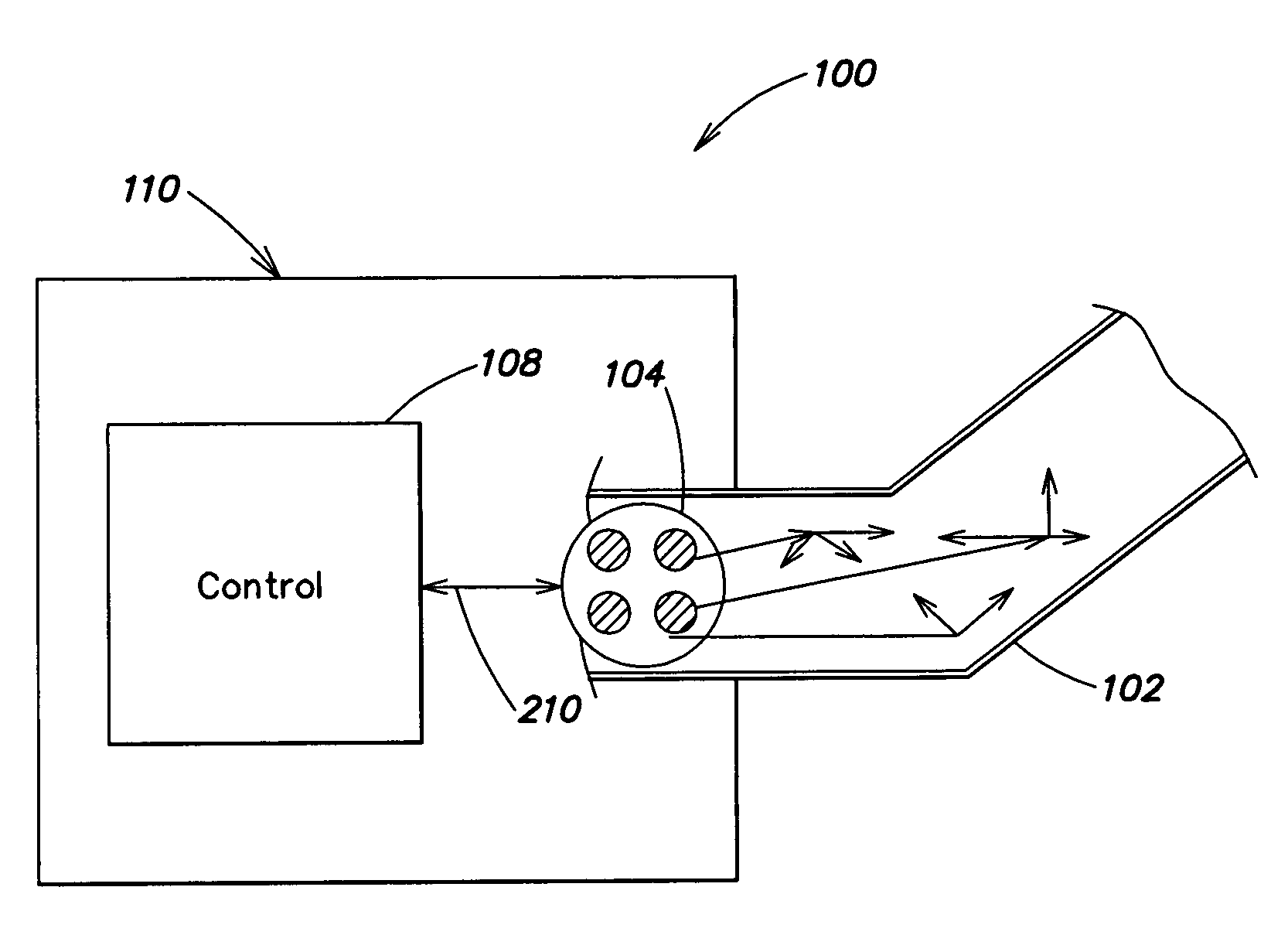
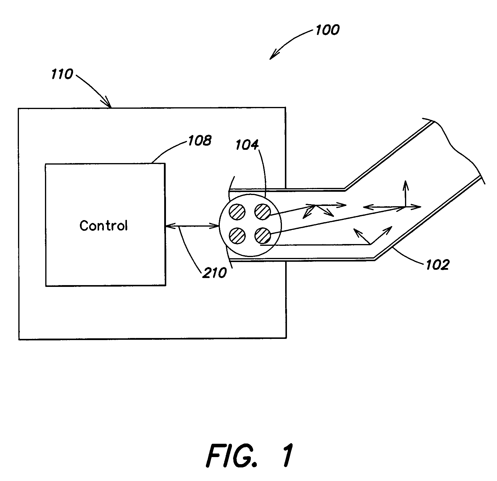
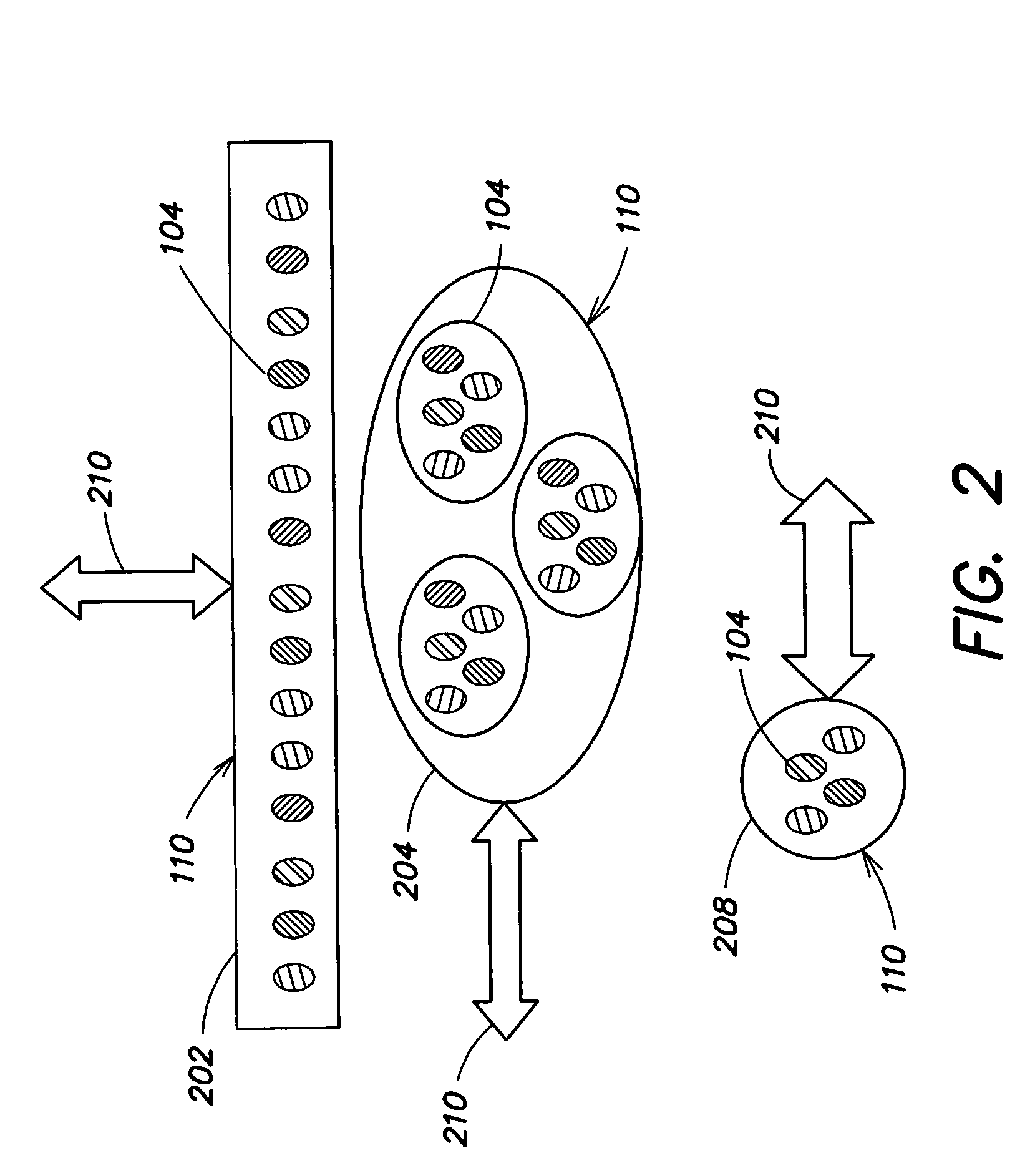
[0076]FIG. 1 depicts a light system 100 with a modular conduit 102 for receiving illumination from a light 104. The light 104 is controlled by a controller 108 to produce light of a desired color, intensity, saturation, color temperature or other characteristic at each point in time. The controller 108 and light 104 comprise a light engine 110. A light 104 coupled with a controller 108 and some kind of interface 210 (which may include a user interface) can be described as a light engine 110, light module, light system or the like. The term light engine 110 thus can describe a light under control of a controller 108, as well as other configurations for generating light. Light engines 110 can also be of greater complexity, as described in connection with FIG. 4.

[0077]In embodiments, the lights 104 are LEDs of different colors (which may include different color temperatures of white LEDs), which can, under control of the controller 108, produce light as desired. In the methods and syst...


PUM


Abstract

Provided herein are methods and systems for preparing signs and displays. The methods and systems include using a light engine for generating light of a plurality of colors to illuminate the body of a flexible conduit that receives light from the light engine. The conduit can be used as a sign, display, or similar lighting facility in many applications that traditionally used neon signs and displays.

Description

CROSS-REFERENCES TO RELATED APPLICATIONS[0001]The present application claims the benefit, under 35 U.S.C. §119(e), of U.S. Provisional Application Ser. No. 60 / 415,897, filed Oct. 3, 2002, entitled “Methods and Apparatus for Illuminating Environments.”[0002]This application also claims the benefit, under 35 U.S.C. §120, as a continuation-in-part (CIP) of U.S. Non-provisional Application Ser. No. 10 / 325,635, filed Dec. 19, 2002, entitled “Controlled Lighting Methods and Apparatus.”[0003]Each of the foregoing applications is hereby incorporated herein by reference.BACKGROUND[0004]Recent years have seen rapid developments in the field of lighting systems. For example, traditional lighting sources such as incandescent, metal halide, neon and fluorescent sources have been joined by fiber optic lights and semiconductor-based light sources such as LEDs in wide use. LEDs, once confined to low-luminosity applications, have become much brighter, and a wider range of LED colors are now availabl...

Claims


Application Information

Patent Timeline
IPC IPC(8): F21V7/04A01M1/04H05B44/00
CPCH05B33/0863A01M1/04H05B45/20H05B47/175
Inventor MUELLER, GEORGE G.DOWLING, KEVIN J.LYS, IHOR A.CELLA, CHARLES H.
Owner SIGNIFY NORTH AMERICA CORP
Learn More