
Lift-out device for pitless well adapters

a technology for lifting out tools and adapters, which is applied in the direction of drilling pipes, well accessories, drilling casings, etc., can solve the problems of not providing sufficient light, unable to illuminate the threads of the adapter sufficiently to be a reliable aid, and difficult to see the threaded connector on the pitless adapter body and thread the lift-out tool to such adapter body

Inactive Publication Date: 2007-11-27
KOCHER JASON
View PDF23 Cites 6 Cited by
  • Summary
  • Abstract
  • Description
  • Claims
  • Application Information

AI Technical Summary

Benefits of technology

[0033]It is a still further object of the invention to provide a lift-out device or tool for attachment to a pitless adapter for a water well system having an integral illumination means whereby said illumination means aids a worker in threadably connecting said to the pitless adapter in an otherwise dark and narrow well casing.
[0034]It is a still further object of the invention to provide a lift-out device or tool for attachment to a pitless adapter for a water well system having an integral illumination means whereby said illumination means aids a worker in connecting the tool to said adapter after which the water pump connected via a well pipe to said adapter assembly may be more quickly and easily removed for servicing, and then after servicing is completed the removable portion of the pitless adapter body may be more easily reconnected to the portion permanently secured to the well casing.
[0035]It is a still further object of the invention to provide a light in a pitless adapter tool which is protected from damage during use and storage and which will illuminate the field of operations particularly when threading the tool to the pitless adapter as well as when threading is accomplished.
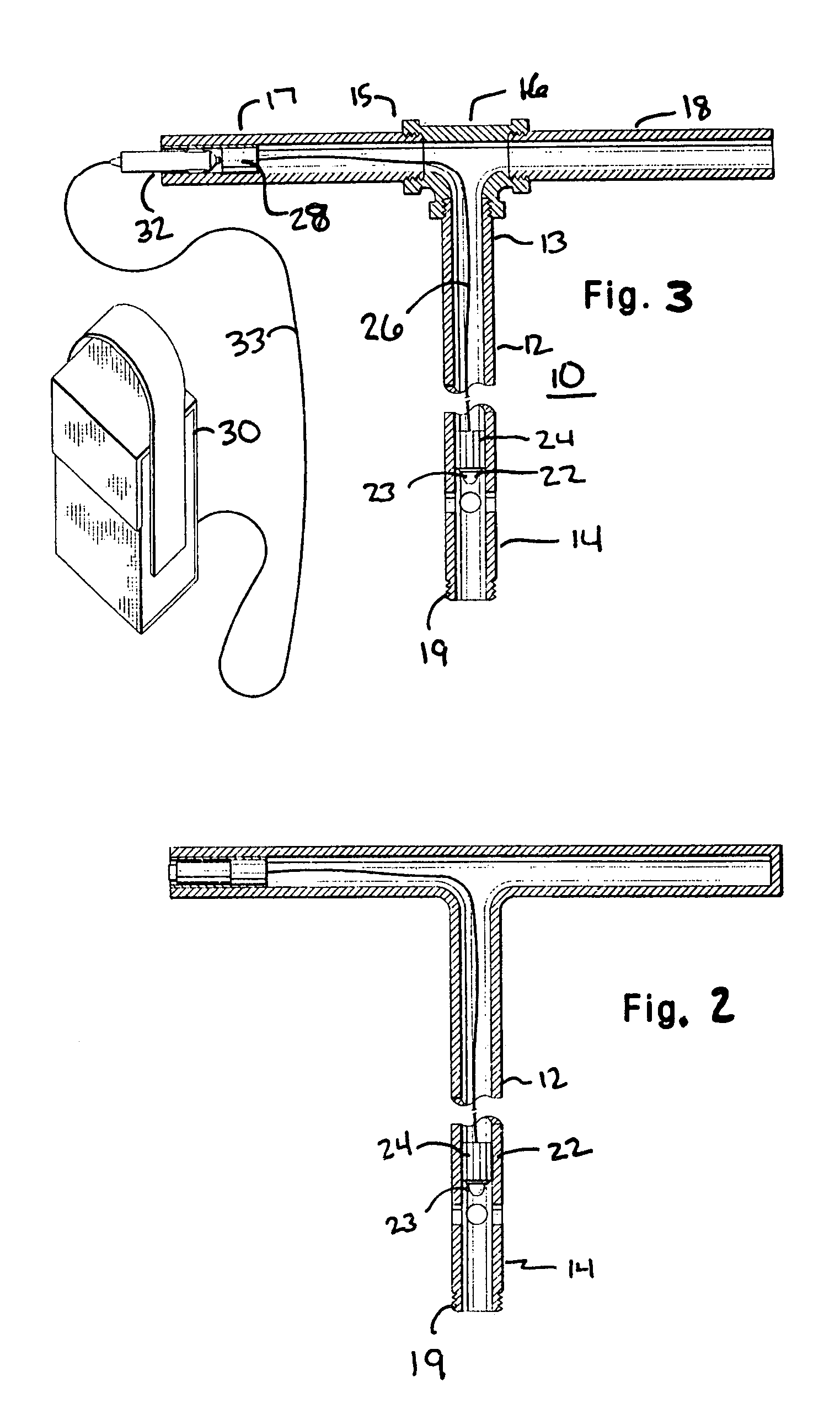
[0037]A tool for attachment to and withdrawal of a pitless adapter in a well environment is provided with a light source in the hollow interior of the tool such that the light illuminates the field of operations both when connected to the pitless adapter and such that the light source is protected from shocks and damage both during rough usage of the tool and during storage between uses. The light is cushioned within the tool and multiple openings in the tool are provided for illumination of the field of use.

Problems solved by technology

A significant problem arises in manually connecting a lift-out device to the pitless adapter body inside the well casing.
Because the pitless adapter is several feet down and substantially inside the well casing, which is itself essentially a deep, dark, narrow hole, it is very difficult to see the threaded connector on the pitless adapter body and to thread the lift-out tool to such adapter body.
This technique fails because the usual flashlight beam can only travel a few feet into the hole before dispersing into darkness, and the mirror also usually does not provide sufficient light and is useful only on sunny days.
A flashlight, mirror and similar devices, usually therefore will not illuminate the threads of the adapter sufficiently to be a reliable aid.
In addition, it is difficult and cumbersome for a single person to hold a flashlight pointed into the well casing in one hand while steadying the lift pipe and threading it to the adapter body with only the other hand.
Thus, threading the pipe into the adapter becomes a hit or miss affair, which is both inconvenient and time consuming, and usually requires two workers, one to hold the flashlight and one to thread the lift-out tool to the adapter.
The shortcoming of this device is in the inability of a flashlight light beam to illuminate a deep hole as the beam of emitted light will travel only a short distance from the lens of the flashlight.
Although each may be useful for its particular purposes, none of the aforementioned references teach or disclose an improved pitless adapter lift-out tool that can be more easily attached to a pitless well adapter for use in removing a water pump from a water well, wherein the improvement comprises an integrated illumination means for lighting the interior of a water well casing.

Method used


Image

  • Lift-out device for pitless well adapters
  • Lift-out device for pitless well adapters
  • Lift-out device for pitless well adapters

Examples


Embodiment Construction

[0043]The following detailed description is of the best mode or modes of the invention presently contemplated. Such description is not intended to be understood in a limiting sense, but to be an example of the invention presented solely for illustration thereof, and by reference to which in connection with the following description and the accompanying drawings one skilled in the art may be advised of the advantages and construction of the invention.

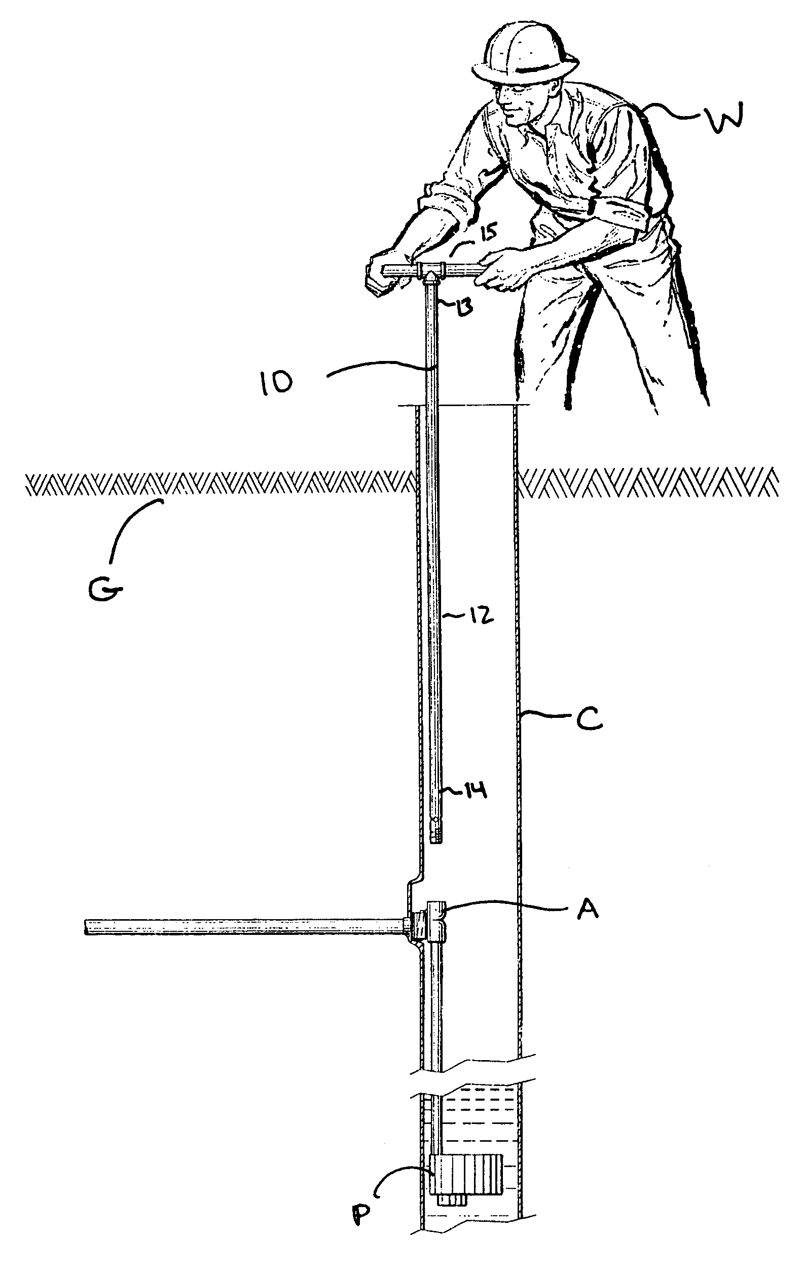
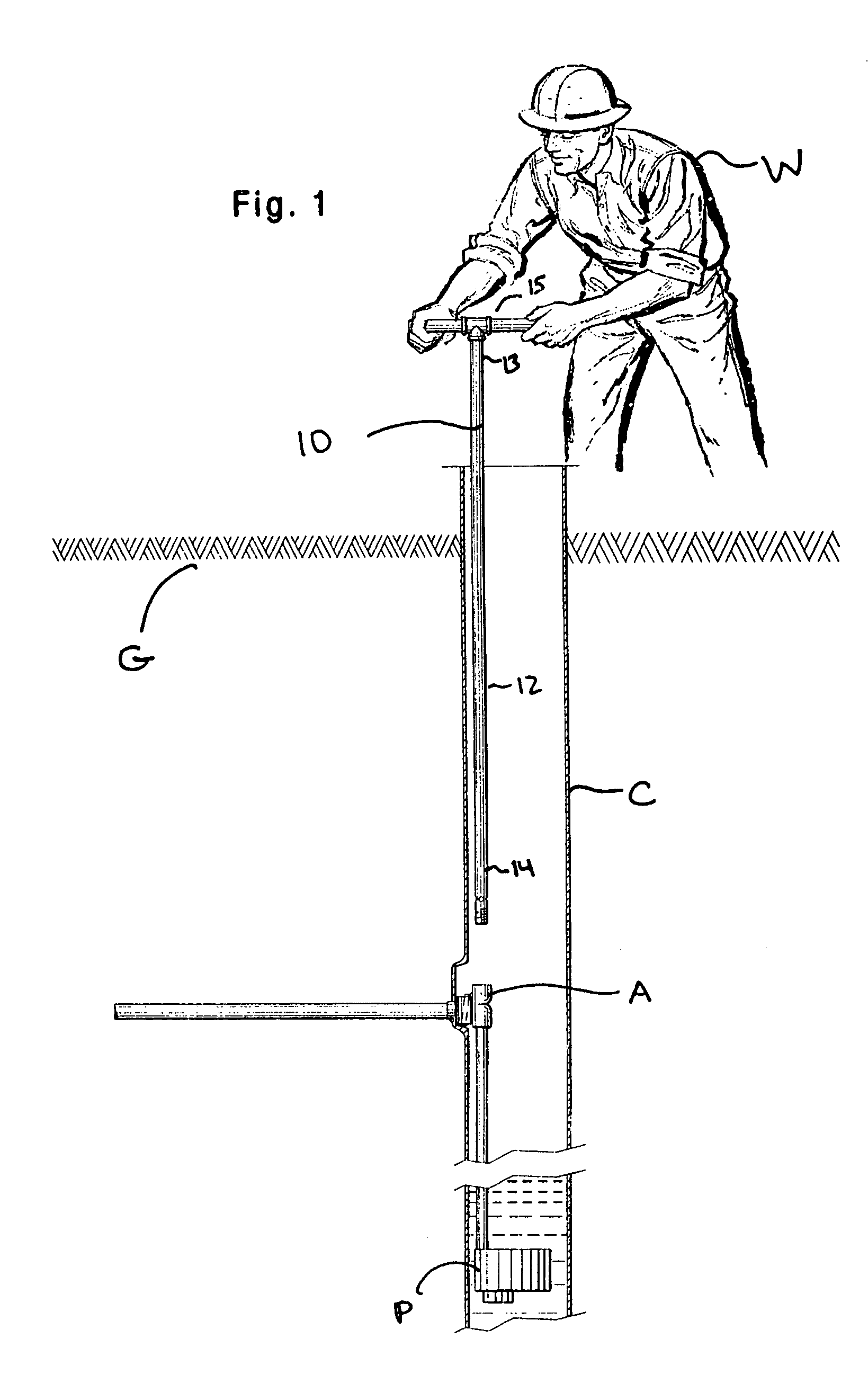
[0044]Referring now to FIG. 1, there is shown a well pump P suspended in well casing C by pitless adapter assembly A connected to a side wall of casing C several feet below ground level G, below the freeze line. Water is pumped upwardly by well pump P and then is diverted horizontally through pitless adapter assembly A and is piped to a home inlet or the like, not shown. Also shown in FIG. 1 is a worker W holding the improved pitless adapter lift-out device 10 of the invention extending downwardly into well casing C. Lift-out device 10 i...


PUM


Abstract

A lift-out device for attachment to a pitless adapter in a water well assembly for use when servicing well pumps including a light source mounted near the lower end of the lift-out device for illuminating the interior of a well casing to facilitate attachment of the device to a pitless adapter. Apertures are located in the side of the tubular pipe member adjacent the light source, and a socket for electrically connecting said light source to an external power source such as a rechargeable battery pack is preferably mounted in the handle of the device. The illumination device is preferably cushioned in order to prevent breakage during use and storage.

Description

BACKGROUND OF THE INVENTION[0001]1. Field of the Invention[0002]The present invention relates generally to water well systems as well as pitless well pipe adapters, and more particularly to an improved lift-out tool for attachment to a pitless well adapter fitting for raising and lowering said adapter and the submersible water pump connected thereto into and from the well casing, and more particularly still to a lift-out tool for attachment to a pitless well adapter having an integral illumination means for facilitation of the attachment procedure.[0003]2. Background of the Invention[0004]A so-called pitless adapter is a specialized pipe fitting that is secured to a well casing below ground, beneath the frost line. The bottom end of the pitless adapter is connected by piping to a water pump suspended within the well, such that well water pumped upwardly from the well pump through the adapter may be diverted horizontally through a hole in the casing and piped to a house or home or ot...

Claims


Application Information

Patent Timeline
IPC IPC(8): E21B19/16
CPCE21B23/00E21B41/00E21B33/00
Inventor KOCHER, JASON
Owner KOCHER JASON
Learn More