
Methods and apparatus for improved phase switching and linearity in an analog phase interpolator

a phase interpolator and linearity technology, applied in pulse manipulation, pulse technique, instruments, etc., can solve the problems of large area and power, slow time it takes to switch from one phase to another desired phase, and the transistor drain not turning back on and reaching steady state. , to achieve the effect of improving phase switching and linearity

Inactive Publication Date: 2007-11-20
AVAGO TECH WIRELESS IP SINGAPORE PTE
View PDF5 Cites 17 Cited by
  • Summary
  • Abstract
  • Description
  • Claims
  • Application Information

AI Technical Summary

Benefits of technology

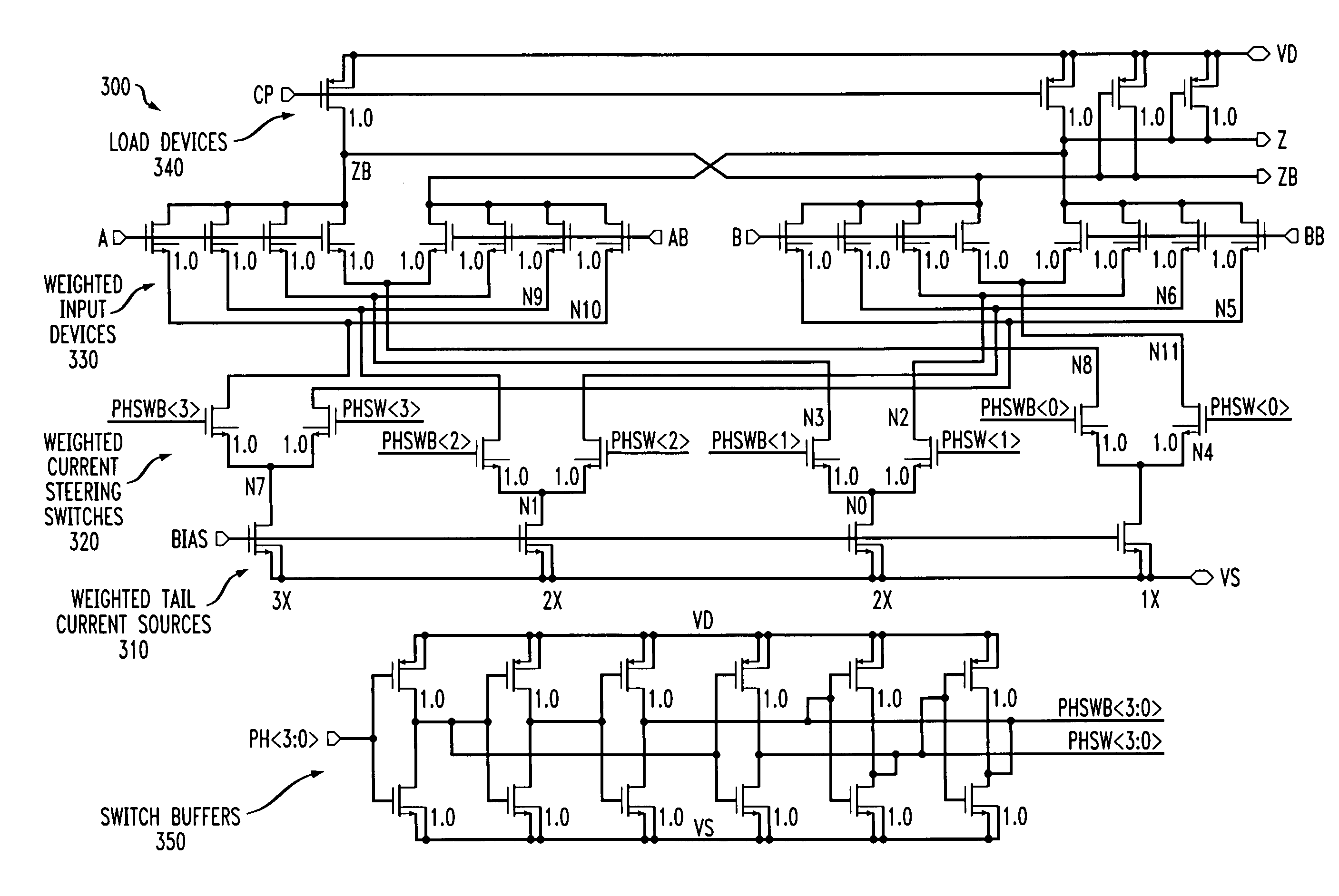
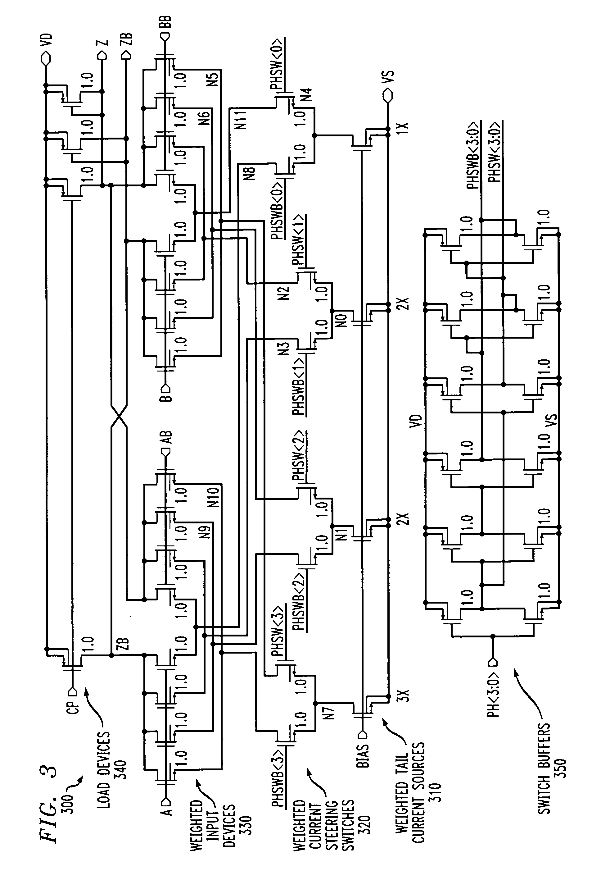
[0006]Generally, methods and apparatus are provided for improving phase switching and linearity in an analog phase interpolator. A phase interpolator in accordance with the present invention comprises (i) a plurality of tail current sources that are activated for substantially all times when the phase interpolator is operational; (ii) at least two pairs of input transistor devices, wherein one pair of the input transistor devices is associated with a minimum phase of the phase interpolator and another pair of the input transistor devices is associated with a maximum phase of the phase interpolator; and (iii) a plurality of current steering switches that provide currents generated by the plurality of tail current sources to one or more of the at least two pairs of input transistor devices, based on an applied interpolation control signal.

Problems solved by technology

Such an array of 2N interpolators, however, consumes considerable area and power, especially as the number of interpolated phases increases.
When a given current source is turned off, however, it takes time for the transistor drain to turn back on and reach steady state.
With 90 nM transistor technology, for example, it has been found that the time it takes to switch from one phase to another desired phase is too slow (on the order of greater than 500 ps).

Method used


Image

  • Methods and apparatus for improved phase switching and linearity in an analog phase interpolator
  • Methods and apparatus for improved phase switching and linearity in an analog phase interpolator
  • Methods and apparatus for improved phase switching and linearity in an analog phase interpolator

Examples


Embodiment Construction

[0014]The present invention provides methods and apparatus for generating multiple clock phases, with a highly linear interpolation transfer function, and fast-switching between phases, for data sampling in clock and data recovery (CDR) systems. According to one aspect of the invention, weighted input devices provide linear interpolation over a wide range of operating frequencies.

[0015]FIG. 1 is a schematic block diagram of a conventional phase interpolator 100. As shown in FIG. 1, an input clock signal is applied to a delay stage 110 to generate two phase offset clock signals that are applied to the input of the analog phase interpolator 100. The input clock signal may be generated, for example, by a local voltage controlled oscillator (VCO) or a voltage controlled delay loop (VCDL). The analog phase interpolator 100 generates an interpolated clock signal 130 having a desired phase in response to an interpolation control code 140, in a known manner. For example, an interpolation co...


PUM


Abstract

Methods and apparatus are provided for improving phase switching and linearity in an analog phase interpolator. A phase interpolator in accordance with the present invention comprises (i) a plurality of tail current sources that are activated for substantially all times when the phase interpolator is operational; (ii) at least two pairs of input transistor devices, wherein one pair of the input transistor devices is associated with a minimum phase of the phase interpolator and another pair of the input transistor devices is associated with a maximum phase of the phase interpolator; and (iii) a plurality of current steering switches that provide currents generated by the plurality of tail current sources to one or more of the at least two pairs of input transistor devices, based on an applied interpolation control signal.

Description

FIELD OF THE INVENTION[0001]The present invention is related to techniques for clock and data recovery (CDR) techniques and, more particularly, to techniques for improving the switching times and linearity of phase interpolators.BACKGROUND OF THE INVENTION[0002]In many applications, including digital communications, clock and data recovery (CDR) must be performed before data can be decoded. Generally, in a digital clock recovery system, a reference clock signal of a given frequency is generated together with a number of different clock signals having the same frequency but with different phases. In one typical implementation, the different clock signals are generated by applying the reference clock signal to a delay network. Thereafter, one or more of the clock signals are compared to the phase and frequency of an incoming data stream and one or more of the clock signals are selected for data recovery.[0003]A number of existing digital CDR circuits use voltage controlled delay loops...

Claims


Application Information

Patent Timeline
Patent Type & Authority Patents(United States)
IPC IPC(8): H03K5/13
CPCH03C3/225
Inventor FREYMAN, RONALD L.ZIEMER, CRAIG B.
Owner AVAGO TECH WIRELESS IP SINGAPORE PTE
Learn More