Headrest for motor vehicle

a headrest and motor vehicle technology, applied in vehicle components, pedestrian/occupant safety arrangements, vehicle arrangements, etc., can solve the problems of inconvenient use, inconvenient use, untimely, etc., and achieve the effects of small force, reduced friction, and controlled large locking for

Inactive Publication Date: 2007-11-13
GRAMMER AUTOMOTIVE CZ
View PDF6 Cites 19 Cited by
  • Summary
  • Abstract
  • Description
  • Claims
  • Application Information

AI Technical Summary

Benefits of technology

[0009]It is the object of the invention to develop the prior art headrest so as to provide one that is more functionally reliable and less prone to failure. It is therefore the object of the invention to develop the prior art headrest in such a manner that the locking unit is less prone to failure and relies for operation not only on frictional adherence but preferably on interlocking adherence and is capable of absorbing higher locking forces.
[0010]This object is solved by the headrest having the features of claim 1. On this headrest, the locking unit has either an electromagnet or a piezoelectric drive. Said piezoelectric drive is connected to the crash sensor, it is at least activated by the crash sensor. The electromagnet or the piezoelectric drive provides the necessary stroke for the movable disengagement member to be mechanically moved with respect to the retainer member in such a manner that a mechanical limit stop is overcome. By this arrangement, larger forces as they exist in the form of locking forces between the two structural components and are effected by the drive of the driving unit can finally be controlled with quite small driving forces provided by the electromagnet or the piezoelectric drive. The releasing forces may be kept all the more small if the moving members are in mutual contact through rollers and rolling elements. Therefore, the invention aims at avoiding any sliding friction between the disengagement member and the retainer member and at providing a construction such that the only friction that occurs is a rolling friction. Therefore, the retainer member and the disengagement member are contacting each other through rolling elements only, more specifically through balls only, at least in the normal case.
[0013]Preferably, the locking unit is actuated upon rotation and / or in the y direction. By this arrangement, the locking unit is prevented from being subjected to heavy load in the event of strong vertical accelerations such as when the vehicle drives over a step or a bump. Preferably, the release motion applied by the electromagnet or the piezoelectric drive also occurs in a direction transverse to the direction in which the second structural component moves away from the first structural component.
[0014]In a first embodiment, the disengagement member has a circumferential groove mating the balls. In the normal case, the balls engage the groove. The retainer member surrounds the balls and has an inner contour the balls fit against. The inner contour further has bight portions extending outward and providing space for the balls. Upon rotation of the inner contour, the balls clear the way by entering said bight portions. As a result, they come free from the groove and the disengagement member can be moved with respect to the retainer member. The retainer member is thereby caused to rotate by the electromagnet or the piezoelectric drive. The electromagnet or the piezoelectric drive may hereby directly drive and, as a result thereof, rotate the disengagement member, but it is also possible to bias the disengagement member by a pressure storing means such as a torsion spring and to provide a nose against which the electromagnet or the piezoelectric drive abut in the normal case. A small movement away from the nose then suffices to release the torsion spring which in turn causes the retainer member to rotate thus allowing the connection between the retainer member and the disengagement member to come free.
[0017]Friction can be considerably reduced by having the levers carried on balls, more specifically by having all the hinges carried on balls, so that the pair of levers can be actuated with little force by the piezoelectric drive or the electromagnet, that is to say that it is possible to control large locking forces.

Problems solved by technology

For practical operation however, such a magnetic clamp is not safe enough.
This however is useless, untimely and incommodes the passengers.
Another disadvantage of the prior art magnetic clamp is that the cooperating surfaces have to very accurately match.

Method used


Image

  • Headrest for motor vehicle
  • Headrest for motor vehicle
  • Headrest for motor vehicle

Examples


Embodiment Construction

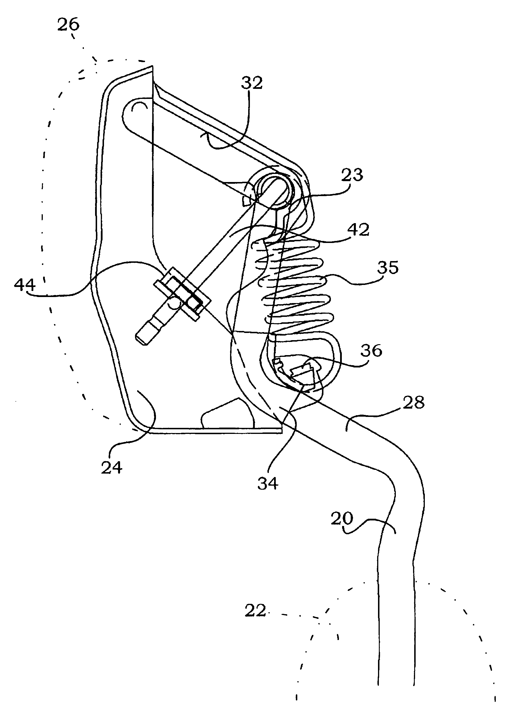
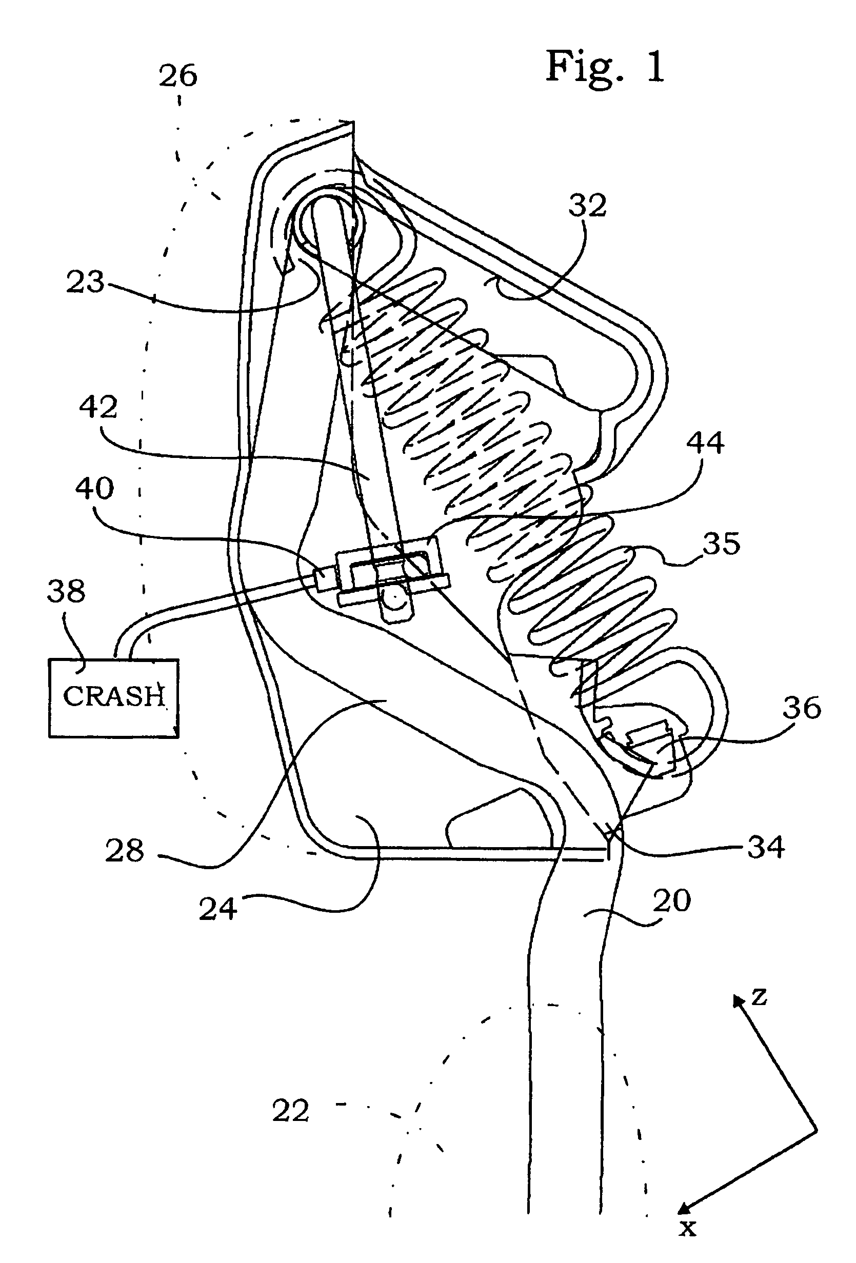
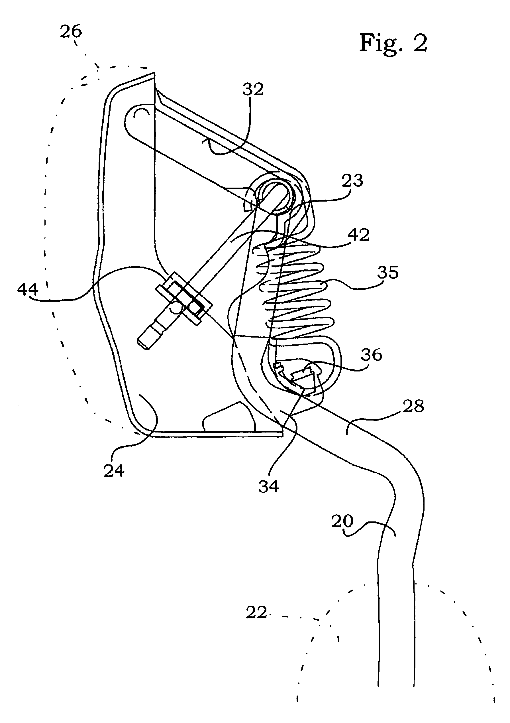
[0029]The headrest has two bars 20 that are retained in a seat back 22. In their uppermost region, the bars 20 are joined by a crossbar 23 to form a generally U-shaped one-piece member. Said U-shaped one-piece member belongs to a first structural component. The U-shaped member carries a supporting body 24 which, in the exemplary embodiments, is substantially made from a plastic part. This supporting body 24 will be discussed in further detail herein after. Finally, the headrest typically has a padding 26 which is illustrated in FIG. 1 and is carried by the supporting body. Supporting body 24 and padding 26 belong to a second structural component that is movable with respect to the first structural component. The movement becomes apparent when comparing e.g., the FIGS. 1 and 2.

[0030]The bars 20 have an inclined portion 28. In this portion, they deviate from the normal direction in which they protrude from the seat back 22 and which is oriented substantially in the z direction so as t...


PUM


Abstract

The headrest has a first structural component for fastening the headrest to a seat back of a motor vehicle seat and a second structural component that is movable with respect to said first structural component in the event of a crash. A drive unit is disposed between the first structural component and the second structural component and comprises a locking unit, which is locked in the normal case, and a crash sensor connected to the locking unit which it controls. The locking unit comprises a disengagement drive with an electromagnet or a piezoelectric drive. The locking unit has one retainer member associated with the first structural component and one movable disengagement member associated with the second structural component. Retainer member and disengagement member are connected together via a hinge or via balls. The disengagement drive is capable of causing said disengagement member to move.

Description

CROSS-REFERENCE TO RELATED APPLICATIONS[0001]This application claims priority to German Application No. DE 10 2005 000 756.2, filed Jan. 4, 2005, the contents of which are hereby expressly incorporated by reference in their entirety as part of the present disclosure.BACKGROUND[0002]The invention relates to a headrest for a motor vehicle having the features of the preamble of claim 1.[0003]A such type headrest is known from DE 102 15 054 A1. The first structural component is intended to be secured to a seat back of a motor vehicle seat, said first structural component including at least one bar. The second structural component comprises a bolster and if necessary further structural elements. In the normal state, the second structural component and as a result thereof the bolster as well, are in a normal position. In the event of a crash, the second structural component moves forward and, as a result thereof, gets in closer proximity to a passenger's head. This arrangement prevents wh...

Claims


Application Information

Patent Timeline
IPC IPC(8): B60N2/42
CPCB60N2/4861B60N2/4885B60N2/4864B60N2/862B60N2/865B60N2/888
Inventor THIEL, THOMASSTEINMETZ, ROLFBECKER, BURKHARD
Owner GRAMMER AUTOMOTIVE CZ
Why Eureka
Try Eureka