
Tower crane device

a technology of lifting device and tower crane, which is applied in the direction of cranes, etc., can solve the problems of reducing the usable space of the building, reducing the construction cost, and requiring a substantial amount of construction materials and labor, so as to save construction costs, minimize construction down time, and efficiently jump the crane

Inactive Publication Date: 2007-11-06
FEDERATED EQUIP
View PDF42 Cites 18 Cited by
  • Summary
  • Abstract
  • Description
  • Claims
  • Application Information

AI Technical Summary

Benefits of technology

[0011]Because the lateral and vertical load is principally distributed vertically to the vertical columns rather than horizontally, no reinforcement of the horizontal beams, floors or any other portion of the building structure are needed, which results in substantial cost savings.
[0012]According to another principles of the present invention, a lifting device uses a lifting frame and a lifter to efficiently jump the crane to minimize construction down time.

Problems solved by technology

As persons of ordinary skill in the art can appreciate, however, these added features involve a substantial amount of additional construction materials and labor solely to accommodate the tower crane.
As a result, construction cost increases substantially and the added space of the extra construction materials reduces the usable space of the building.
Moreover, conventional crane lifting systems are cumbersome to operate, often requiring an entire day or more to jump the crane, resulting in substantial construction down time.

Method used


Image

  • Tower crane device
  • Tower crane device
  • Tower crane device

Examples


Embodiment Construction

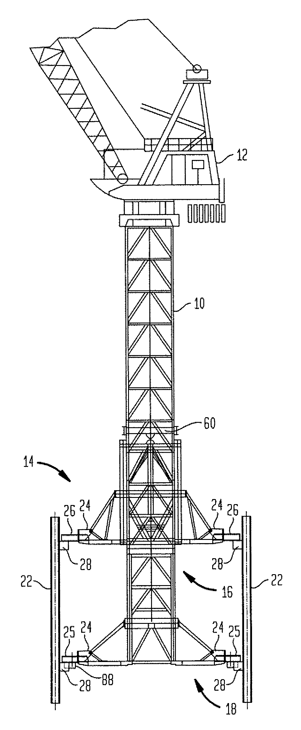
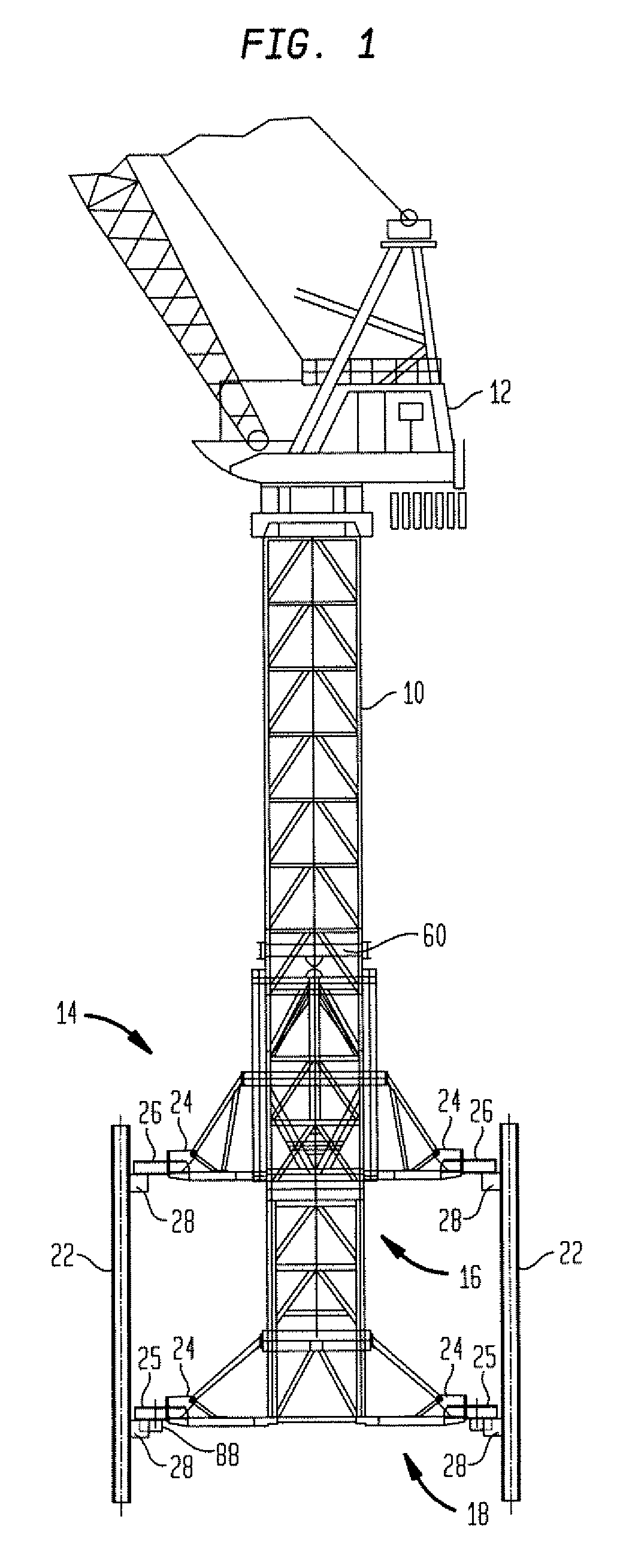
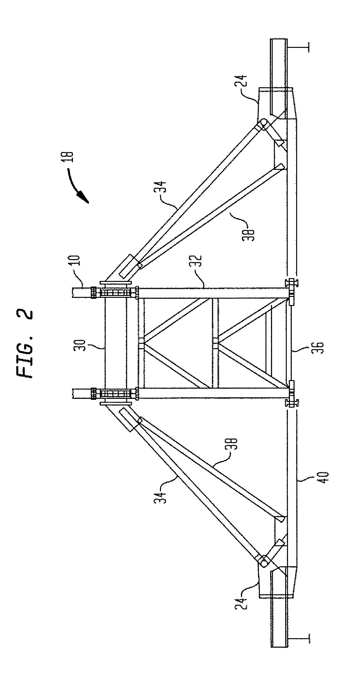
[0029]Generally, the type of tower crane lifting devices to which this invention relates is positioned within a bay of a building under construction. Illustrated in FIG. 1 is a tower 10 supporting a crane 12. The combination of the tower 10 and the crane 12 are often called a tower crane. The tower 10 is being supported by a lifting device 14 according to the present invention which is positioned within four vertical columns 22 (only two are shown) of a bay. The lifting device 14 includes an upper base or basket 16, a lower base or basket 18, and a rectangular lifting or climbing frame 60 for jumping the tower 10. The upper basket 16 and the lifting frame 60 surround and are vertically slidable with respect to the tower 10. The tower 10 rests on and is attached to the lower basket 18. Each basket 16, 18 has four outriggers 24 having slidable foot members 25. The outriggers 24 are operated by a hydraulic pump (not shown). The upper and lower baskets 16, 18 rest upon support stubs 28 ...


PUM


Abstract

A crane tower device includes a basket that supports a tower crane and sits within a bay formed by the vertical columns of a building under construction. The basket and the tower crane are supported by support stubs that are attached to the vertical columns. Because the lateral and vertical load is principally distributed vertically to the vertical columns rather than horizontally, no reinforcement of the horizontal beams, floors or any other portion of the building structure are needed, which results in substantial cost savings.

Description

FIELD OF THE INVENTION[0001]The present invention relates to tower cranes, and more particularly, tower crane lifting devices.BACKGROUND OF THE INVENTION[0002]As is well-known, tower cranes are used in constructing buildings. Some are free-standing, but the types of tower cranes to which this invention relates are generally positioned within the building under construction, supported by the building structure, usually passing through aligned floor slab openings created for this purpose. The tower of the tower crane is usually supported from one floor, extending upward through aligned openings in all completed upper floors. As construction of the building progresses and the floors approach the boom of the crane, the tower, crane and boom must be raised or “jumped” to a higher elevation.[0003]For jumping the tower, one system previously in common use employed a hydraulic cylinder connected to a specially equipped lower mast section, with an additional cross piece connected to the cyli...

Claims


Application Information

Patent Timeline
Patent Type & Authority Patents(United States)
IPC IPC(8): B66C23/18B66C23/32B66C23/34
CPCB66C23/32
Inventor DAVIS, LARRYHOWARD, LARRYSCHIAVONI, MICHAEL
Owner FEDERATED EQUIP
Learn More