
Image processing device

a technology of image processing and image, applied in the field of image processing methods, can solve the problems of color loss, color is not reproduced accurately, and the chroma is reduced even for color signals, and achieve the effects of reducing the occurrence of false colors, high luminance, and high accuracy

Inactive Publication Date: 2007-10-30
SEIKO EPSON CORP
View PDF3 Cites 2 Cited by
  • Summary
  • Abstract
  • Description
  • Claims
  • Application Information

AI Technical Summary

Benefits of technology

The present invention aims to solve the problem of false color in images by restraining its occurrence and preserving the original color signals. The first invention proposes a method for mapping color signals to an achromatic axis defined on the basis of an arbitrary illuminant, while the second invention proposes a method for mapping color signals with preserving continuity of chroma, not only for saturated color signals but also for color signals surrounding them. These methods can effectively restrain the occurrence of false color and reproduce gradations of chroma of the original color signals with high accuracy.

Problems solved by technology

Thus, in a photographed image, as a result of signal values of colors reaching saturation not simultaneously but rather sequentially, in areas of high luminance, there can occur the phenomenon of “false color” whereby color that is not inherently present in the area is applied to it, so that color is not reproduced accurately.
However, with the technique mentioned above, since gain is suppressed over a wide spectrum, chroma becomes reduced even for color signals that are not at saturation.
Accordingly, in a high luminance area having a luminance signal above a certain level, chroma is suppressed completely so that tone gradations cannot be preserved, resulting in the problem of color loss.

Method used


Image

  • Image processing device
  • Image processing device
  • Image processing device

Examples


first embodiment

A. First Embodiment

A1. System Arrangement

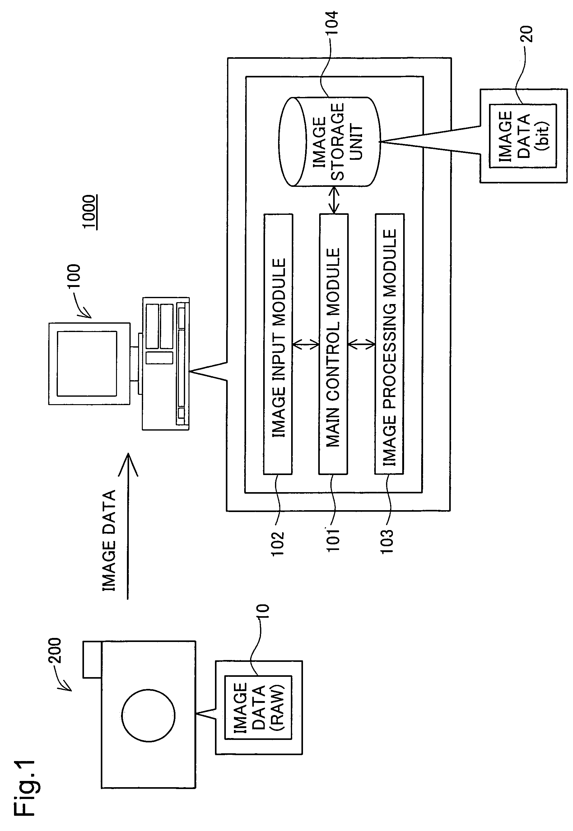
[0038]FIG. 1 is an illustration explaining in exemplary fashion the system arrangement of the image processing system 1000 of the first embodiment. The image processing system 1000 includes an image processing device 100 and a digital camera 200. The digital camera 200 has a CCD as the image sensor. The digital camera 200 is able to shoot images. Shot images are created in RAW format, and recorded as image data 10 on a memory card, not shown. In the first embodiment, a CCD is provided as the image sensor, but it would be possible instead to employ a CMOS (Complementary Metal Oxide Semiconductor) or the like.

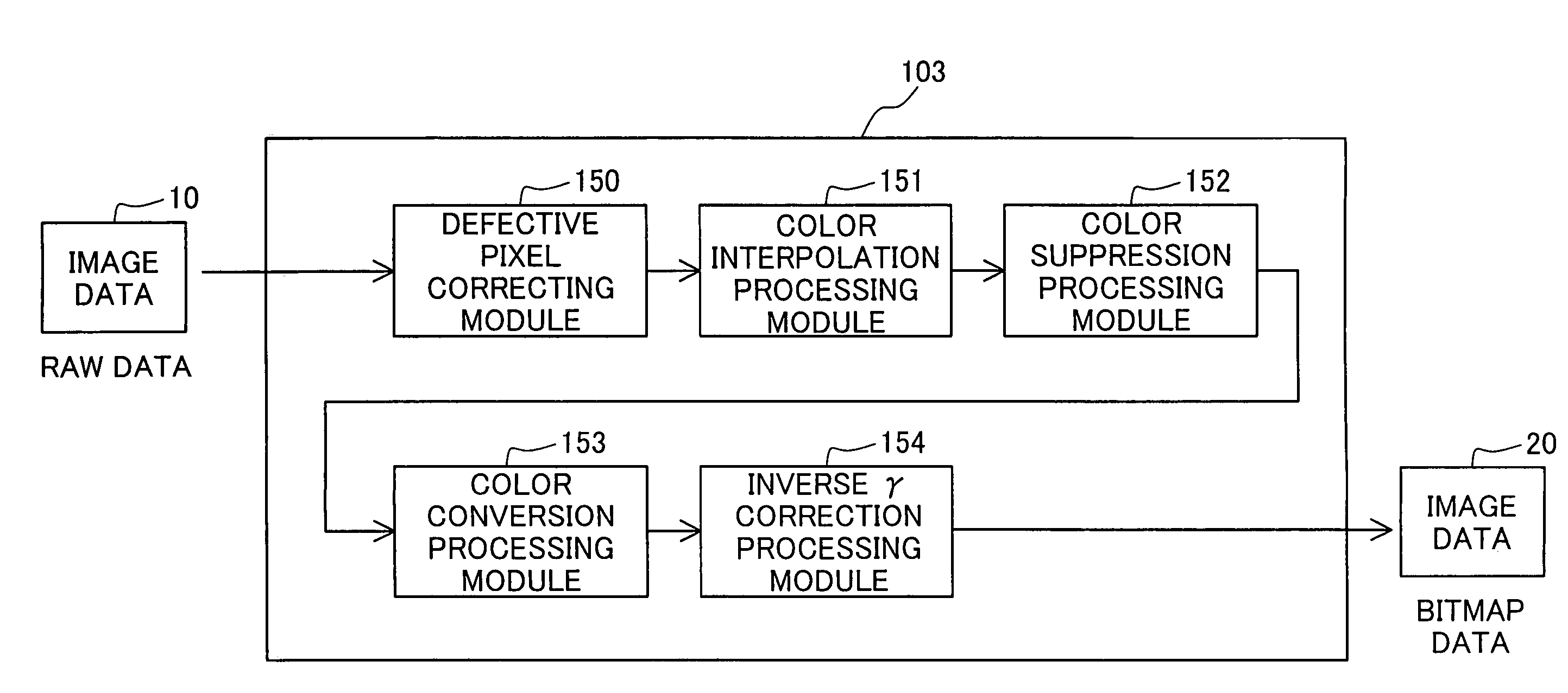
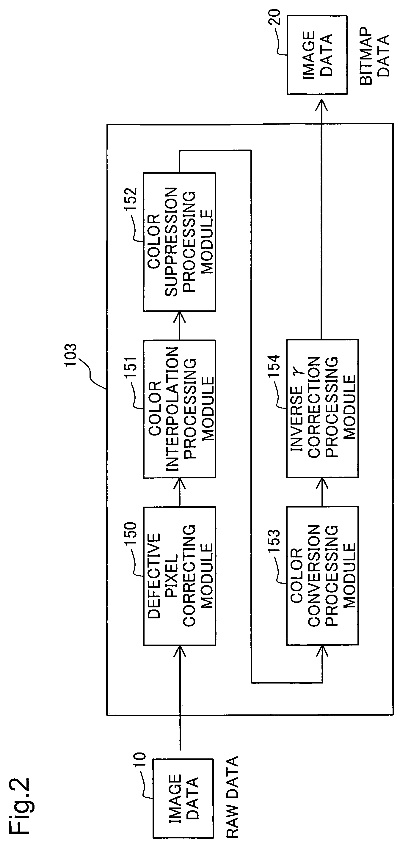
[0039]The image processing device 100 is an ordinary computer. When the image processing device 100 is input image data 10 from the digital camera 200. The image processing device 100 performs image processing including color suppression processing on the image data 10, and converts it to image data 20 of bitmap format.

[0040]The functional...

second embodiment

B. Second Embodiment

[0081]In the first embodiment, the color suppression process is performed using Rg, Gg, Bg which denote R, G, B color component ratios when an achromatic color subject is photographed. In the second embodiment, the color suppression process is performed with consideration given to gain level used in the white balance process. The white balance process is a process for preventing a photographed image from assuming color cast different from the actual color of the subject due to a different illuminant, and is executed by multiplying the color component values by different gain levels, depending on the illuminant.

[0082]In this second embodiment, the process indicated below is performed. Using gain level established in association with any particular specified illuminant, adjustment is performed such that R, G, B color component values of coordinate points on the achromatic axis are identical, and the achromatic axis is established on an identical axis to an achromat...


PUM

PropertyMeasurementUnit
coloraaaaaaaaaa
colorsaaaaaaaaaa
areaaaaaaaaaaa

Abstract

The image processing device of the present invention maps signal values on saturation segments to corresponding signals on an achromatic axis. In conjunction with this, mapping of color signal present around the saturation segments is mapped while preserving the continuity prior to mapping. The image processing device determines the displacement level entailed in mapping color signal surround a saturation segment so as to be inversely proportional to distance from the saturation segments. Since chroma of signals on the saturation segments change precipitously before and after mapping, by mapping signal surround the saturation segments so as to preserve the continuity of the original signals of signals surround the saturation segments, chroma gradation of signals on the saturation segments and signals around saturation segments can be preserved with a high degree of accuracy.

Description

BACK GROUND OF THE INVENTION[0001]1. Field of the Invention[0002]The present invention relates to an image processing method, and relates in particular to color suppression of photographed images.[0003]2. Description of the Related Art[0004]In recent years, digital cameras that use CCDs (Charge Coupled Devices) to shoot images have become widespread. Transmittance of a pass filter of the imaging element differs by color, and color saturation signal values differ by color as well. Thus, in a photographed image, as a result of signal values of colors reaching saturation not simultaneously but rather sequentially, in areas of high luminance, there can occur the phenomenon of “false color” whereby color that is not inherently present in the area is applied to it, so that color is not reproduced accurately.[0005]In order to address this problem, there has been disclosed a technique of using luminance information in a photographed image to suppress color signal gain in high luminance area...

Claims


Application Information

Patent Timeline
Patent Type & Authority Patents(United States)
IPC IPC(8): H04N1/48G03F3/08G06K9/48G09G5/02H04N9/68G06K9/00H04N9/73G06T1/00H04N1/46H04N1/60H04N5/232H04N101/00
CPCH04N1/6027H04N9/735H04N1/6086H04N23/88
Inventor FUKASAWA, KENJIIMAI, SHUN
Owner SEIKO EPSON CORP
Learn More