
Illumination system having at least two light sources, and a method for operating such an illumination system

a technology of illumination system and light source, which is applied in the direction of electric variable regulation, process and machine control, instruments, etc., can solve the problems of long switch-on and switch-off time, high switching loss, and unsatisfactory interference, etc., and achieve high switching loss

Inactive Publication Date: 2007-10-30
PATENT TREUHAND GESELLSCHAFT FUER ELECTRIC GLUEHLAMPEN M B H
View PDF5 Cites 10 Cited by
  • Summary
  • Abstract
  • Description
  • Claims
  • Application Information

AI Technical Summary

Benefits of technology

Enables variable brightness without interference or high switching losses, allowing for stable color output and extended service life in applications like motor vehicle headlights, while supporting dimmable and mood-adjustable lighting.

Problems solved by technology

However, one problem consists in that with some LEDs, in particular with InGaN LEDs, there is a more or less strong relationship between the current intensity of the conducting-state current IF and the associated wavelength of the emitted light.
Upon transition to higher powers, however, as is required in the case of lamps for general lighting or use in a motor vehicle, undesired interference can arise.
If this limit is adhered to, this results in very long switch-on and switch-off times and, in association therewith, very high switching losses.
Thus, with the measures known from the prior art, a decision has to be made for one of the evils, either interference or color locus displacements or high switching losses.

Method used


Image

  • Illumination system having at least two light sources, and a method for operating such an illumination system
  • Illumination system having at least two light sources, and a method for operating such an illumination system

Examples


Embodiment Construction

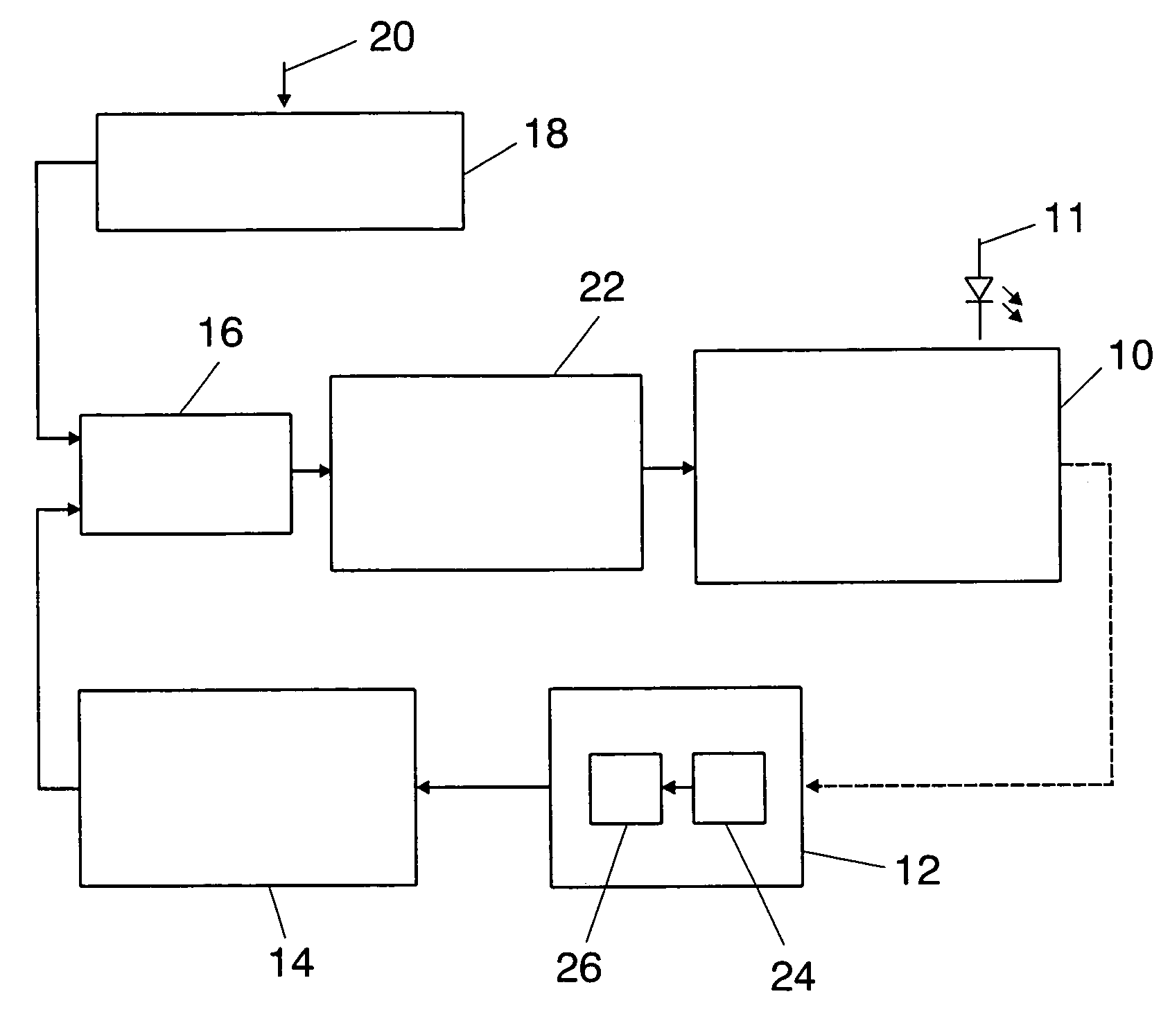
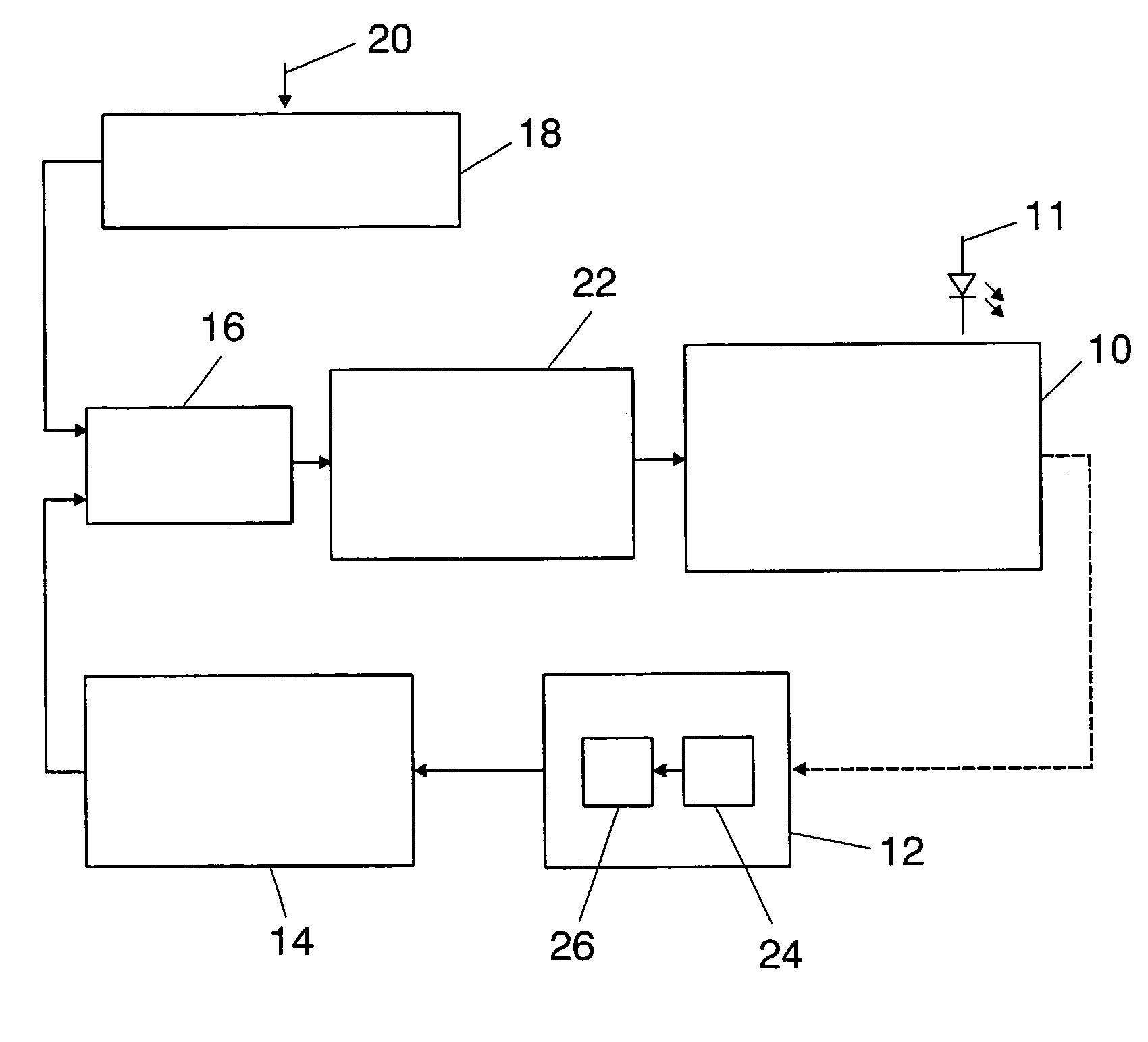
[0021]FIG. 1 shows a schematic of an illumination system according to the invention. It comprises a number of light sources that are combined in a block 10, at least one light source being—as illustrated schematically—an LED 11 that is operated with a DC signal. The light output by the block 10 is sensed by a sensor device 12 with the aid of which at least one feature of the light output by the illumination system can be determined. The color temperature, the brightness or the color locus come into consideration as features. The at least one feature determined by the sensor device 12 is stored in an actual value storage device 14. The actual value storage device 14 can be designed for storing the values of a number of features. The actual value of the at least one feature is made available to a control device 16. The latter is also provided by a setpoint selection device 18 with a setpoint of the at least one feature. This device can also be designed for storing a multiplicity of va...


PUM


Abstract

An illumination system has at least two light sources of which at least one light source includes an LED, and a driver device designed to operate at least the one LED with a DC signal; a sensor device for determining at least one feature of the light output; an actual value storage device connected to the sensor device for storing an actual value of the feature; a setpoint selection device for storing a setpoint of the feature; and a control device connected on the input side to the actual value storage device for of transmitting the actual value, and to the setpoint selection device for transmitting the setpoint, and which provides the driver device with a control signal that changes a characteristic of the DC signal used for driving the LED such that the actual value approaches the setpoint.

Description

FIELD OF THE INVENTION[0001]The present invention relates to an illumination system having at least two light sources of which at least one light source comprises an LED. It relates, moreover, to a method for operating such an illumination system.BACKGROUND OF THE INVENTION[0002]Illumination systems of said type are sufficiently well known in the prior art, the simplest method of operating LEDs consisting in connecting the LED to a DC source together with a series resistor. The series resistor is used to limit the light-emitting diode current IF (conducting-state current). The conducting-state current IF can be varied by varying the series resistor, as the result of which the brightness of the light emitted by the light-emitting diodes is likewise varied. It is possible in this simple way to achieve the dimmability of a system that can comprise light-emitting diodes and other luminous means as light source. However, one problem consists in that with some LEDs, in particular with InG...

Claims


Application Information

Patent Timeline
Patent Type & Authority Patents(United States)
IPC IPC(8): G05F1/00H05B44/00H01L33/00
CPCH05B33/086H05B35/00H05B33/0869H05B45/22H05B45/20
Inventor BIEBL, ALOISHACKENBUCHNER, STEFANHIRSCHMANN, GUNTHERWEITZEL, REINHARD
Owner PATENT TREUHAND GESELLSCHAFT FUER ELECTRIC GLUEHLAMPEN M B H
Learn More