
Method and system of re-directing and backing up security system data at a receiver

a security system and receiver technology, applied in the field of monitoring systems, can solve problems such as data being trapped in the receiver, the printer is broken, and the cable is lost, and achieve the effect of preventing the data from being lost and redirected to the receiver

Active Publication Date: 2007-10-23
ADEMCO INC
View PDF5 Cites 12 Cited by
  • Summary
  • Abstract
  • Description
  • Claims
  • Application Information

AI Technical Summary

Benefits of technology

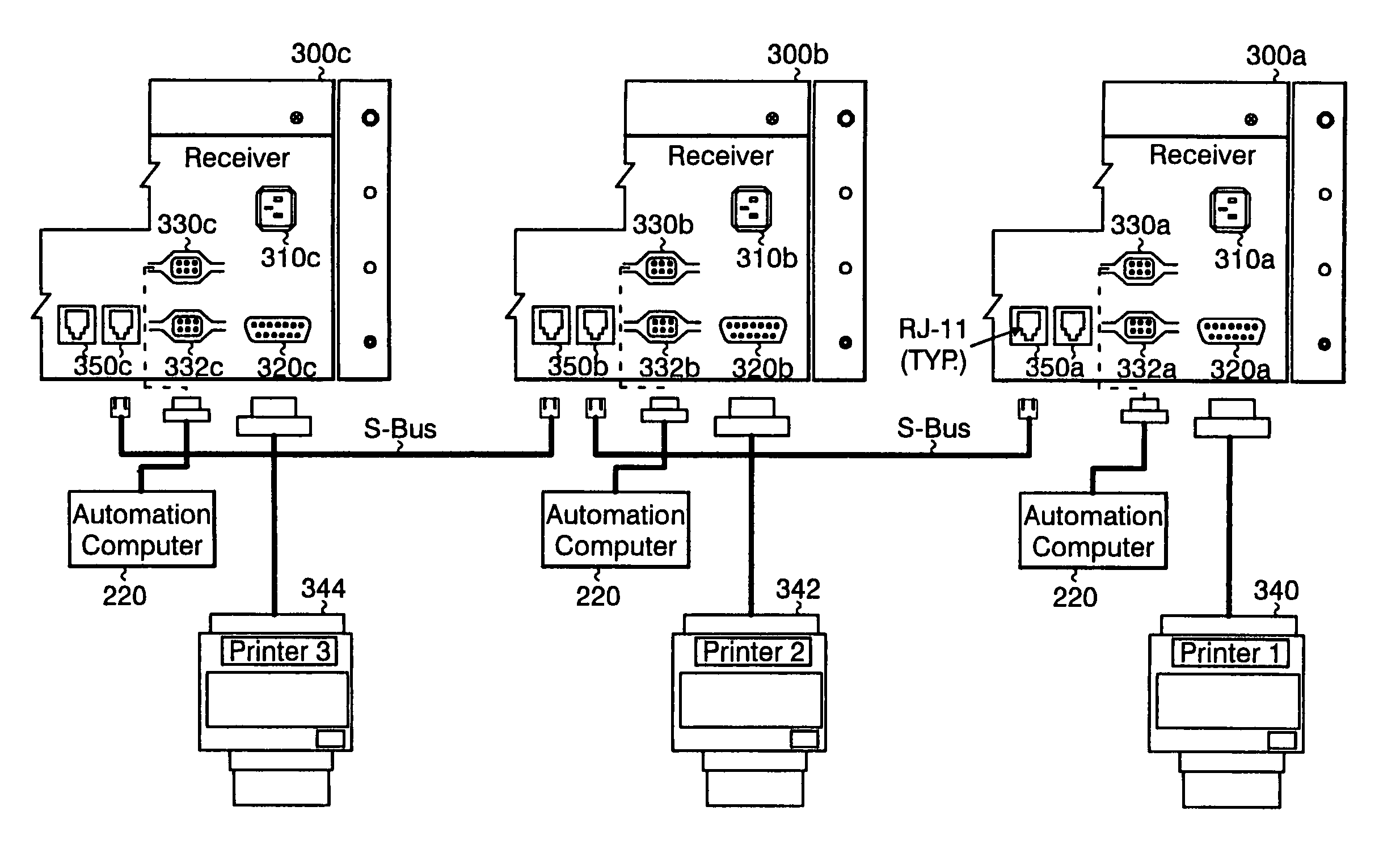
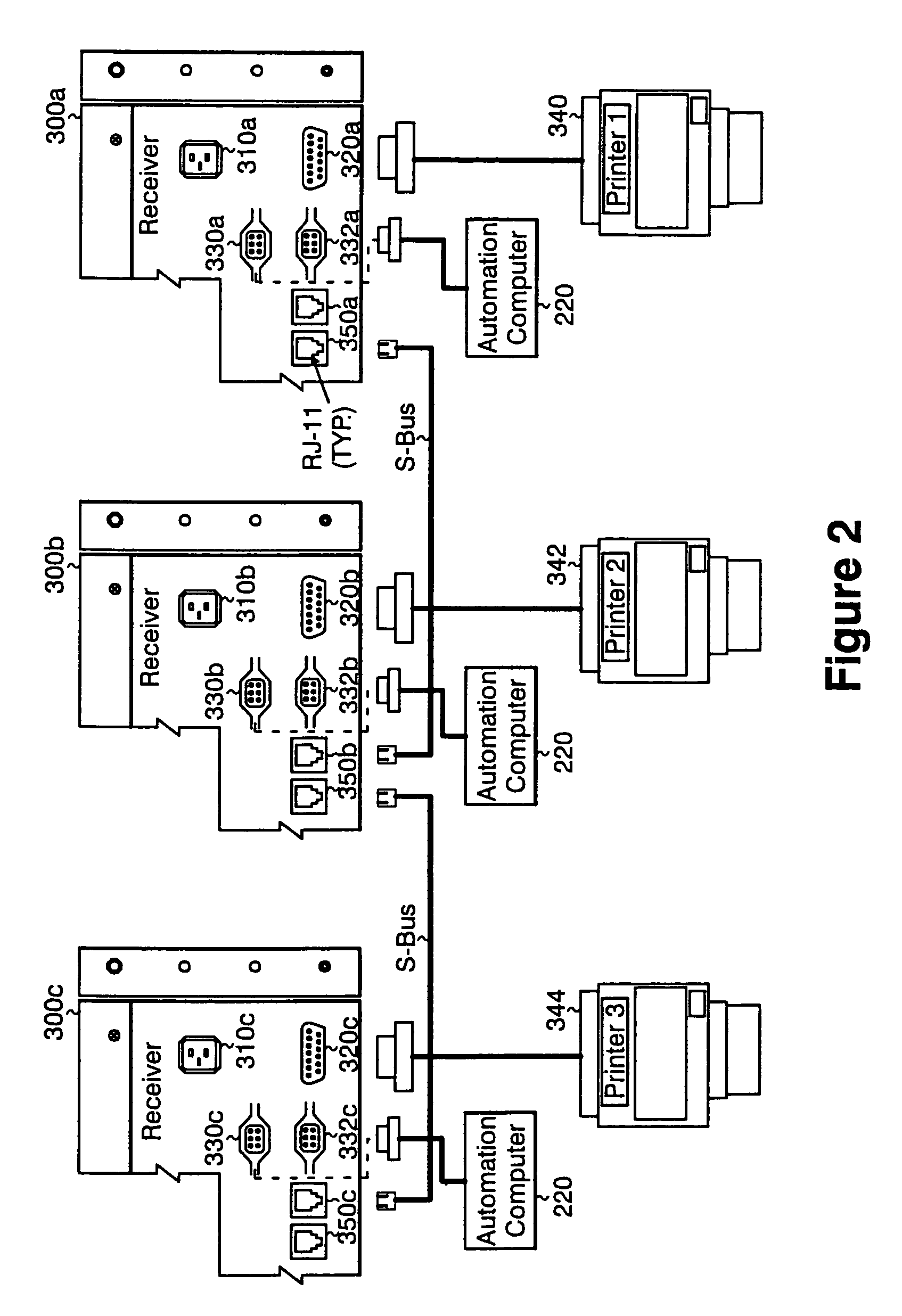
The present invention provides a solution for a monitoring system that allows the receiver to connect to the automation system or printer even if its primary path is blocked, malfunctions, or down. The monitoring system includes a plurality of receivers, an automation computer, and a plurality of printers. The system has at least one primary data path and one backup data path for each receiver. The system automatically switches from the primary data path to the backup data path when there is an error in the primary data path. The system also includes a means for detecting the error and displaying an alarm on the receiver. The invention allows for programming of the primary and backup data paths and determining the status of each path. The technical effect of the invention is to provide a reliable and flexible monitoring system that ensures connectivity even in situations of blockages or malfunctions.

Problems solved by technology

However, there is a need for each receiver to be able to transmit data to the automation computer or print its data on a printer if its primary path to the printer or automation computer is malfunctioning or the port is down, the printer is broken, or cable is lost.
For example, if the primary path to the automation system is down, the data received by the receiver will be trapped in the receiver because the data cannot be transmitted to the automation system for processing.
This may cost additional money for the additional ports and connection.

Method used


Image

  • Method and system of re-directing and backing up security system data at a receiver
  • Method and system of re-directing and backing up security system data at a receiver
  • Method and system of re-directing and backing up security system data at a receiver

Examples


Embodiment Construction

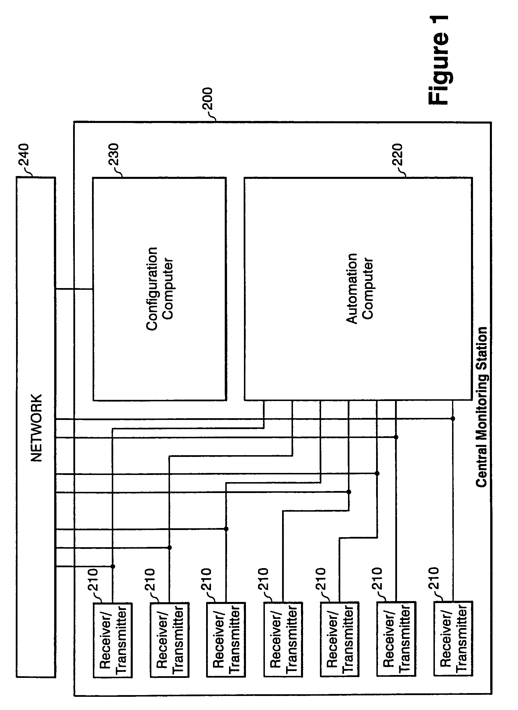
[0022]FIG. 1 illustrates a central monitoring station. The central monitoring station 200 can include a configuration computer 230 that is programmed to upload and download local installed security system configurations. The central monitoring station 200 is typically provided at a staffed facility that is remote from the local installed security systems 100 which it serves. The staff at the central monitoring station 200 may monitor the alarm status of the different security systems and take appropriate actions such as notifying emergency personnel when an alarm is tripped.

[0023]The central monitoring station 200 is connected to the local installed security system via a network or a communication link 240. The communication link can be any means that allows for bi-directional transmission of data. The communication link 240 can include essentially any type of communication path or paths, including a telephone link, such as a conventional telephone network, to communicate with the l...


PUM


Abstract

A monitoring system having a plurality of receivers connected to at least one other receiver such that data can be transmitted from a primary receiver to a backup receiver if a data path to an automation computer or to its printer is down. The system programs a primary data path and at least one backup data path. The system detects an error in the primary data path and determines if a backup receiver's data path is operational. The system automatically transmits data received by a primary receiver to a pre-selected backup receiver based upon an error flag. This allows for each receiver to process calls even though its primary path to the automation system or printer is down or malfunctioning.

Description

FIELD OF INVENTION[0001]The invention relates generally to a monitoring system including a central monitoring station having a plurality of receivers that receive information from a number of different security systems at different locations wherein the receivers are connected to an automation system and printer. More specifically, the invention relates to a monitoring system receiver being connected with multiple receivers such that if a receiver loses connection to its automation system and printer, the data is not lost or isolated from the remaining receivers and automation system.BACKGROUND[0002]Security systems, such as for homes and businesses, have become commonplace as people seek to protect themselves and their property. A security system includes any life, safety, and property protection system. The security system typically includes a central control panel that communicates with a number of sensors via a wired or wireless path. The control panel has the ability to notify ...

Claims


Application Information

Patent Timeline
Patent Type & Authority Patents(United States)
IPC IPC(8): G08B29/00
CPCH04L12/2602H04L43/00H04L43/0811
Inventor MARTIN, CHRISTOPHER D.
Owner ADEMCO INC
Learn More